Digital modules
3.10 Digital input module SM 321; DI 16 x 24 VDC; with hardware and diagnostic interrupts
S7-300 Automation System Module data
Manual, 08/2006, A5E00105505-04
3-27
3.10.2 Parameters of SM 321; DI 16 x DC 24 V
Programming
The general procedure for programming digital modules is described in
Configuring digital
modules
.
Parameters of SM 321; DI 16 x DC 24 V
The table below shows an overview of configurable parameters and their default settings for
SM 321; DI 16 x DC 24 V.
The default settings apply if you have not set any parameters in STEP 7.
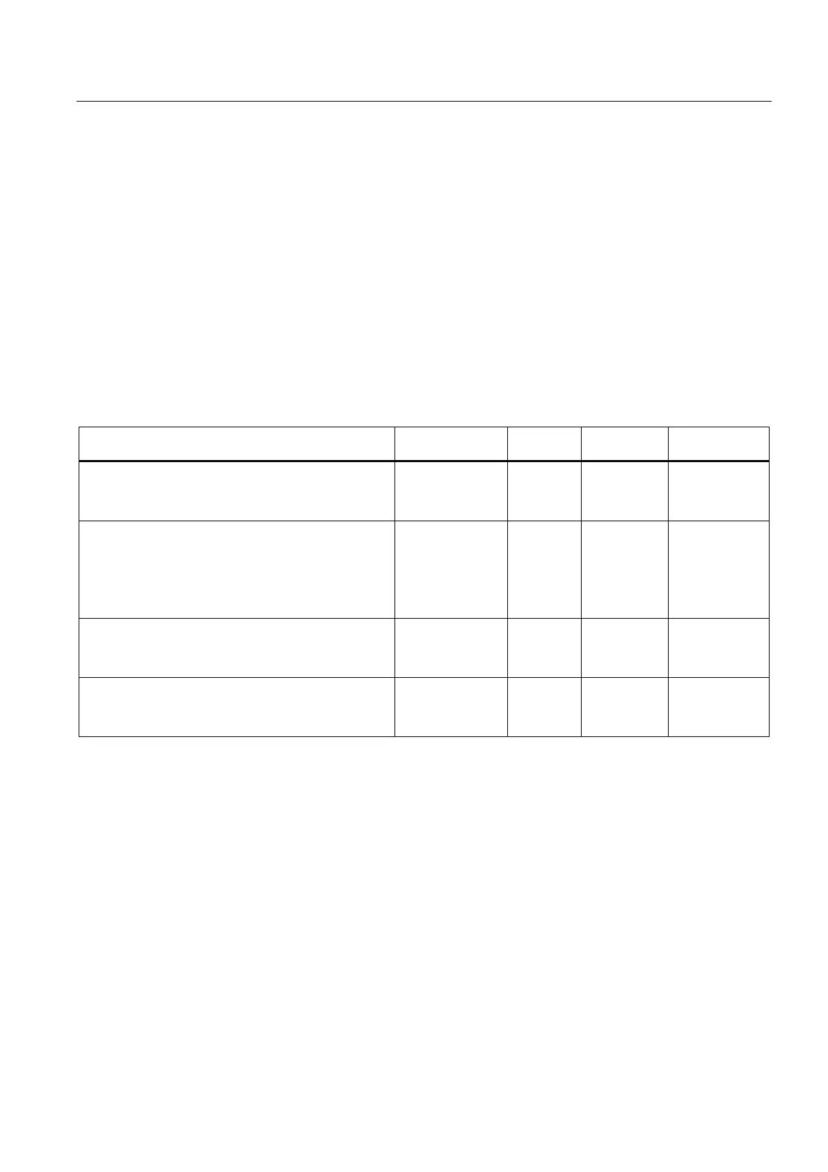
Table 3-8 Parameters of SM 321; DI 16 x DC 24 V
Parameters Range of values Default Parameter
type
Scope
Enable
• Diagnostic interrupt
• Hardware interrupt
Yes/no
Yes/no
No
No
Dynamic
Module
Input delay/voltage type 0.1 ms (DC)
0.5 ms (DC)
3 ms (DC)
15 ms (DC)
20 ms (DC/AC)
(DC) static Module
Diagnostics
• Encoder supply missing
• Wirebreak
Yes/no
Yes/no
No
No
static
Channel group
Hardware interrupt trigger
• Positive edge
• Negative edge
Yes/no
Yes/no
No
No
Dynamic
Channel group
Allocating the encoder supplies to channel groups
The module's two encoder supplies, supply power to two channel groups: Inputs 0 to 7 and
inputs 8 to 15. You also configure diagnostics for the encoder supply at those two channel
groups.
(6ES7321-7BH01-0AB0)
 Loading...


