Analog modules
6.5 Analog input module SM 331; AI 8 x 14 Bit High Speed; synchronous; (6ES7331-7HF0x-0AB0)
S7-300 Automation System Module data
Manual, 08/2006, A5E00105505-04
6-37
6.5.4 Additional information on SM 331; AI 8 x 14 Bit High Speed, isochronous
Unused channels
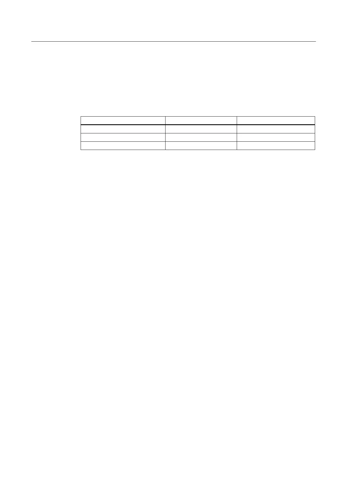
You should wire unused channels as shown in the following table. This optimizes
interference immunity of the analog input module.
Measuring range M+/ M- M_ana
Voltage short-circuit link with M-
Current / 4-wire transducer leave open link with M-
Current / 2-wire transducer leave open link with M
Certain inputs of the channel group configuration may remain unused. To enable diagnostic
functions at the used channels, note the special features of those inputs outlined below:
● Measuring range 1 V to 5 V: wire the used and unused inputs of the same channel group
in parallel.
● Current measurement, 2-wire transducer: There are two options of wiring the channel
circuit.
a) Open unused input; channel group diagnostics disabled. If you were to enable
diagnostics, the analog module would trigger a single diagnostic interrupt, and light up its
SF LED.
b) Loading the unused input using a 1.5 kΩ to 3.3 kΩ resistor. This allows you to enable
diagnostics for this channel group.
● Current measurement 4 mA to 20 mA, 4-wire transducer: wire the unused inputs of the
same channel group in series.
Wire-break check function in the 4 mA to 20 mA measuring range
If you configured a measuring range of 4 mA to 20 mA, and enabled wire-break check, the
analog input module logs a wire-break event in diagnostics data when the current drops
below 1,185 mA.
The module also triggers a diagnostic interrupt if you enabled diagnostics interrupts in the
program.
The lit SF LED is otherwise the only indication of the wire-break, and you must evaluate the
diagnostic bytes in the user program.
If you configured a measuring range of 4 mA to 20 mA, disabled wire-break check, and
enabled diagnostic interrupts, the module triggers a diagnostic interrupt when the underflow
value is reached.

 Loading...


