Digital modules
3.10 Digital input module SM 321; DI 16 x 24 VDC; with hardware and diagnostic interrupts
S7-300 Automation System Module data
3-28 Manual, 08/2006, A5E00105505-04
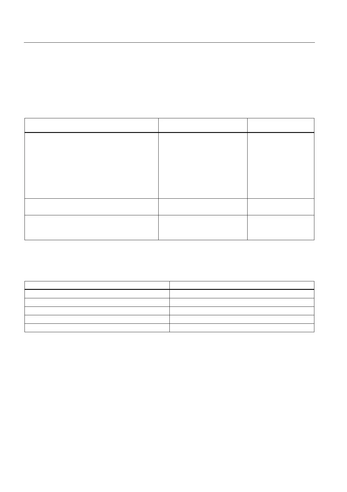
Assigning interrupt parameters to channel groups
The table below shows which channels you can group for interrupt processing.
You will need the channel group number to set the SFC parameters in the user program.
Table 3-9 Assigning interrupt parameters to the inputs of SM 321; DI 16 x DC 24 V
Parameter... configurable in the following channel
groups
Channel group number
Hardware interrupt (triggered by positive, negative, or
both edges)
0 and 1
2 and 3
4 and 5
6 and 7
8 and 9
10 and 11
12 and 13
14 and 15
0
1
2
3
4
5
6
7
Diagnostic interrupt
for missing encoder supply
0 to 7
8 to 15
-
Diagnostic interrupt
for wire-break
0 and 1
2 and 3
0
1
:
Tolerances of the programmable input delays
Table 3-10 Tolerances of the input delays at SM 321; DI 16 x DC 24 V
Programmed input delay Tolerance
0.1 ms 60 μs to 140 μs
0.5 ms 400 ms to 900 ms
3 ms (default) 2.6 ms to 3.3 ms
15 ms 12 ms to 15 ms
20 ms 17 ms to 23 ms
See also
Programming digital modules (Page 3-8)
(6ES7321-7BH01-0AB0)