RS 485 Repeater
9.2 Design of the RS 485 Repeater; (6ES7972-0AA01-0XA0)
S7-300 Automation System Module data
Manual, 08/2006, A5E00105505-04
9-3
9.2 9.2 Design of the RS 485 Repeater; (6ES7972-0AA01-0XA0)
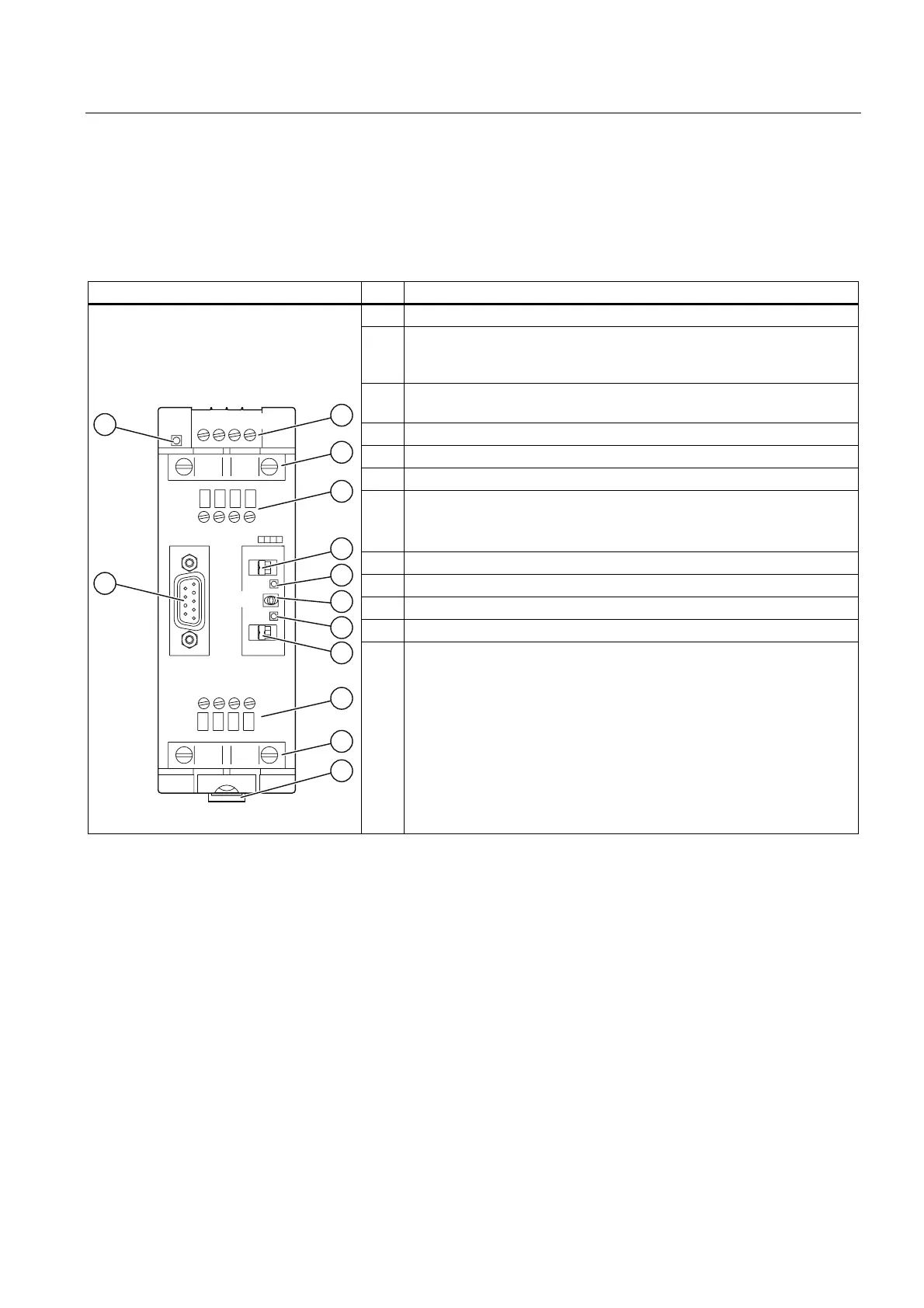
The table below shows the design and functions of the RS 485 Repeater.
Table 9-3 Description and functions of the RS 485 Repeater
Repeater design No. Function
① LED 24 V supply voltage
② Terminal for the RS 485 Repeater power supply (pin "M5.2" is
reference ground, if you want to measure voltage between terminals
"A2" and "B2".)
③ Shield clamp for the strain relief and grounding of the bus cable of bus
segments 1 or 2
④ Terminals for the bus cable of bus segment 1
⑤ Terminating resistance for bus segment 1
⑥ LED for bus segment 1
⑦ OFF switch
(= isolate bus segments from each other, for example, for
commissioning)
⑧ LED for bus segment 2
⑨ Terminating resistance for bus segment 2
⑩ Terminals for the bus cable of bus segment 2
⑪ Slide for mounting and removing the RS 485 Repeater on the DIN rail
'&
9
/ 0 3( 0
6,(0(16
565(3($7(5
21
$ % $ %
$ % $ %
3*
23
'3
2))
21
'3
⑫ Interface for PG/OP on bus segment 1

 Loading...


