Interface modules
8.3 Interface module IM 361; (6ES7361-3CA01-0AA0)
S7-300 Automation System Module data
8-4 Manual, 08/2006, A5E00105505-04
8.3 8.3 Interface module IM 361; (6ES7361-3CA01-0AA0)
Order number
6ES7361 3CA01-0AA0
Properties
Special features of interface module IM 361:
● 24 VDC power supply
● Interface for racks 1 to 3 of the S7-300
● Current output via the S7-300 backplane bus: max. 0.8 A
● Data transfer from IM 360 to IM 361, or from IM 361 to IM 361 via connecting cable 368
● Maximum distance between IM 360 and IM 361 is 10 m
● Maximum distance between IM 361 and IM 361 is 10 m
Status and error LEDs
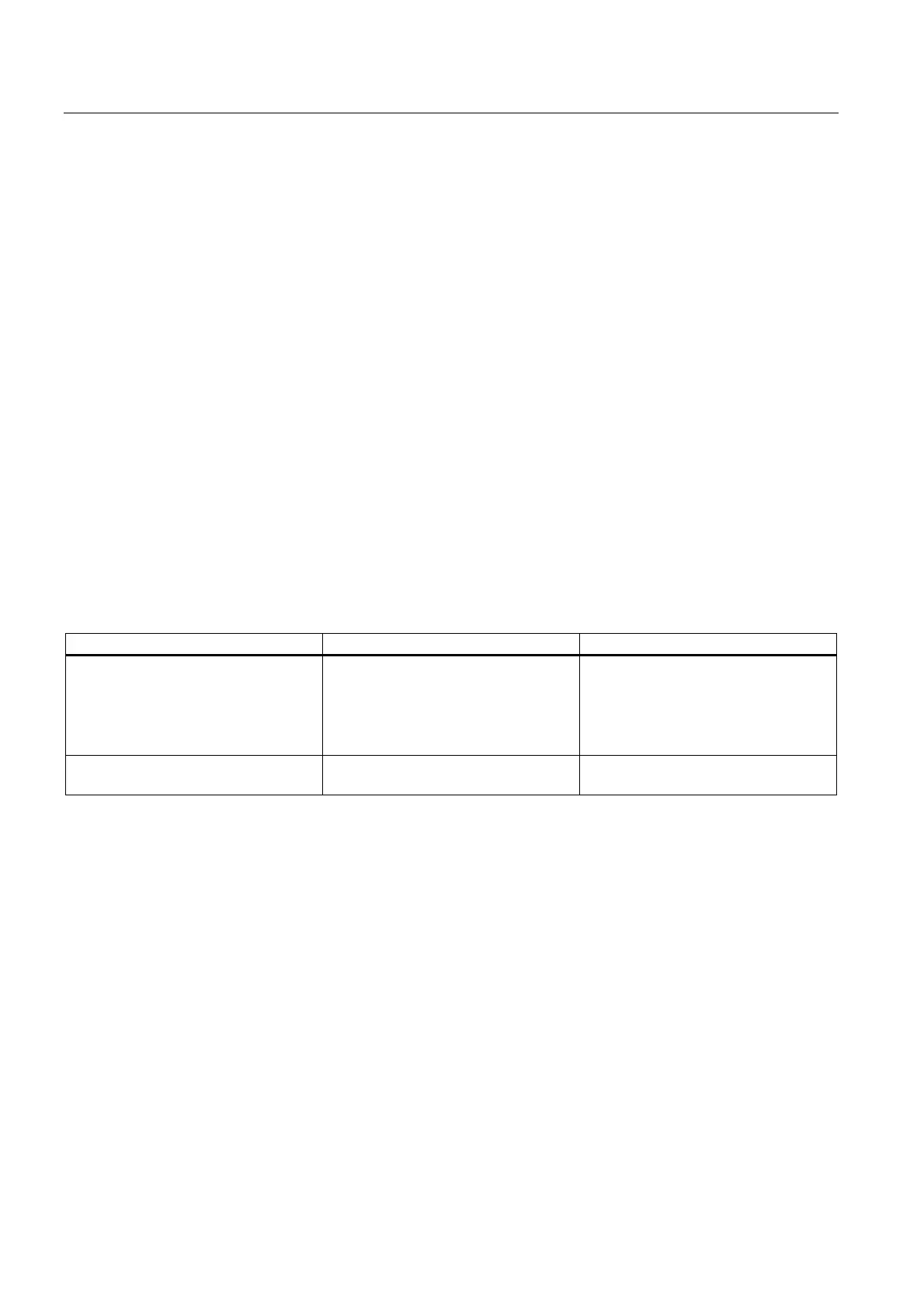
Interface module IM 361 is equipped with the following status and error LEDs.
Display element Meaning Explanations
SF Group error The LED lights up if
• the connecting cable is missing
• the IM 361 connected in series is
switched off
• the CPU is in POWER OFF state
5 VDC 5 VDC supply for the S7-300 backplane
bus
-

 Loading...


