Analog modules
6.5 Analog input module SM 331; AI 8 x 14 Bit High Speed; synchronous; (6ES7331-7HF0x-0AB0)
S7-300 Automation System Module data
6-32 Manual, 08/2006, A5E00105505-04
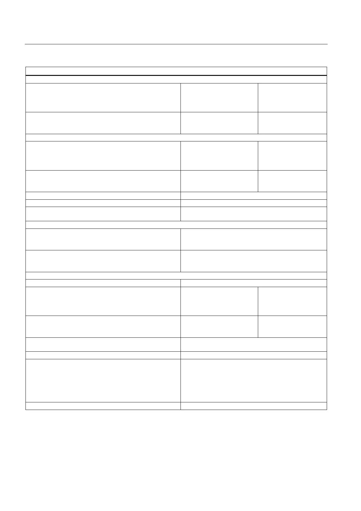
Technical data
Operational limit (across temperature range, relative to input range)
• Voltage input
± 1 V
± 5 V
± 10 V
1 to 5 V
± 0,3 %
± 0,4 %
± 0,3 %
± 0,4 %
• Current input
± 20 mA
0 mA to 20 mA
4 mA to 20 mA
± 0,3 %
± 0,3 %
± 0,3 %
Basic error limit (operational error limit at 25 °C, relative to input range)
• Voltage input
± 1 V
± 5 V
± 10 V
1 to 5 V
± 0,2 %
± 0,25 %
± 0,2 %
± 0,25 %
• Current input
± 20 mA
0 mA to 20 mA
4 mA to 20 mA
± 0,2 %
± 0,2 %
± 0,2 %
Temperature error (relative to input range) ± 0.004 %/K
Linearity error (relative to input range) ± 0,03 %
Repetition accuracy (in transient state at 25 °C, relative to
input range)
± 0,1 %
Status, interrupts, diagnostics
Interrupts
• Hardware interrupt
• Diagnostic interrupt
programmable
programmable
Diagnostics functions
• Group error display
• Reading diagnostics information
red LED (SF)
supported
Transducer selection data
Input ranges (rated values) / input impedance
• Voltage
± 1 V
± 5 V
± 10 V
1 to 5 V
10 MΩ
100 kΩ
100 kΩ
100 kΩ
• Current
± 20 mA
0 mA to 20 mA
4 mA to 20 mA
50 Ω
50 Ω
50 Ω
Permissible voltage at voltage input (destruction limit) max. 20 V continuous; 75 V for the duration of max. 1 s
(duty factor 1:20)
Permissible current at current input (destruction limit) 40 mA
Wiring signal transducers
• for voltage measurement
• for current measurement
as 2-wire transducer
as 4-wire transducer
• Load of the 2-wire transducer at L+ = DC 24 V
with 20-pin front connector
supported
supported
supported
max. 820 Ω
Characteristic linearization None

 Loading...


