Analog modules
6.8 Analog input module SM 331; AI 2 x 12 bit; (6ES7331-7KB02-0AB0)
S7-300 Automation System Module data
6-62 Manual, 08/2006, A5E00105505-04
Terminal assignment
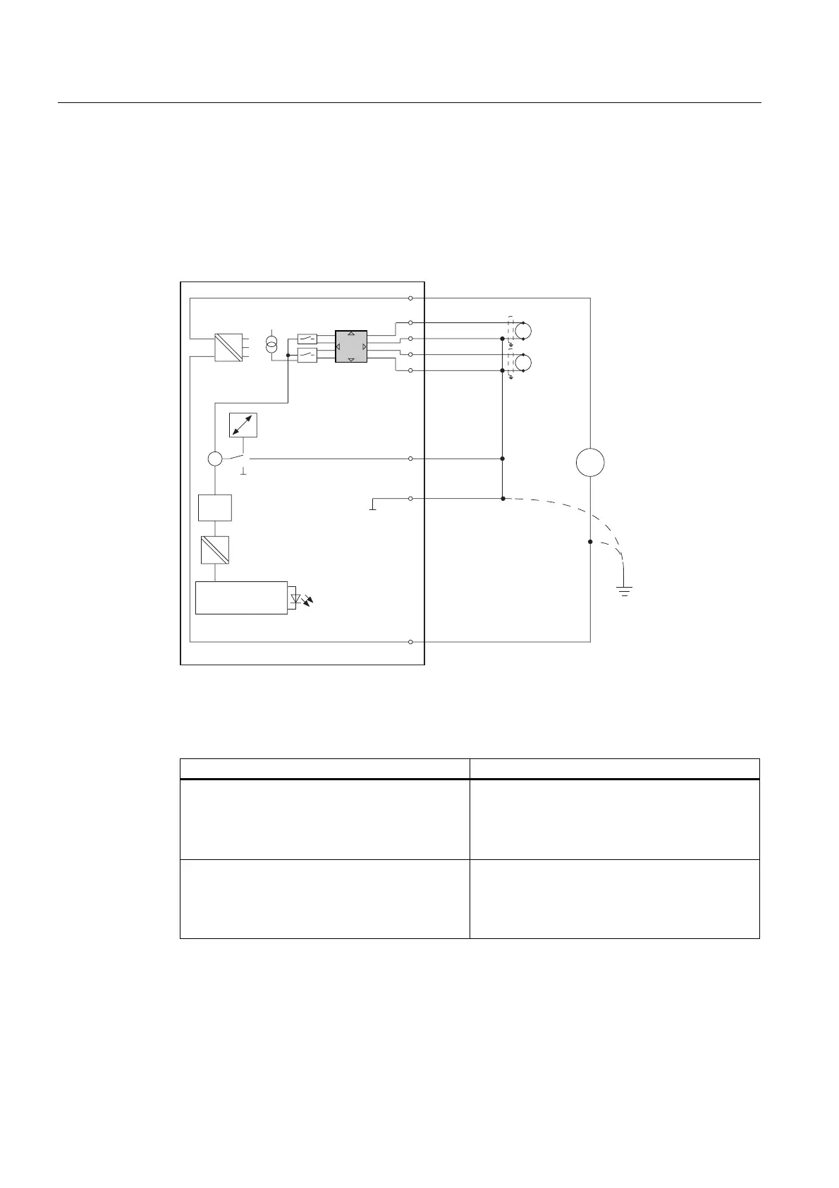
The following diagrams show different possible forms of wiring. The input impedance is
determined by the set measuring range.
Wiring: Voltage measurement
9
'&
/
0
7
6)
0ದ
0ದ
0
0
&RPS
&+
&+
&RPSದ0$1$
9
9
%DFNSODQHEXV
FRQQHFWLRQ
(OHFWULFDO
LVRODWLRQ
,QWHUQDO
VXSSO\
,QWHUQDO
FRPSHQVDWLRQ
([WHUQDOFRPSHQVDWLRQ
1RQH
$'&
&XUUHQW
VRXUFH
0XOWL
SOH[HU
0HDVXULQJ
UDQJHPRGXOHV
(TXLSRWHQWLDO
ERQGLQJ
)XQFWLRQDO
JURXQG
Figure 6-18 Wiring and block diagrams
Measuring range module settings
Measuring range Measuring range module setting
± 80 mV
± 250 mV
± 500 mV
± 1000 mV
A
± 2.5 V
± 5 V
1 V to 5 V
± 10 V
B

 Loading...


