Analog modules
6.10 Analog input module SM 331; AI 8 x TC; (6ES7331-7PF11-0AB0)
S7-300 Automation System Module data
Manual, 08/2006, A5E00105505-04
6-87
Terminal assignment
The following diagrams show wiring examples. These connection examples apply to all
channels (channel 0 to 7).
Wiring: Thermocouple via reference junction
All 8 inputs are available as measurement channels if thermocouples are wired via reference
junctions which are regulated to 0 °C or 50 °C.
9
+
/ದ
'&
'&
0
/
&+
&+
&+
&+
&+
0
0
0
0
0
0
0
0
&+
&+
&+
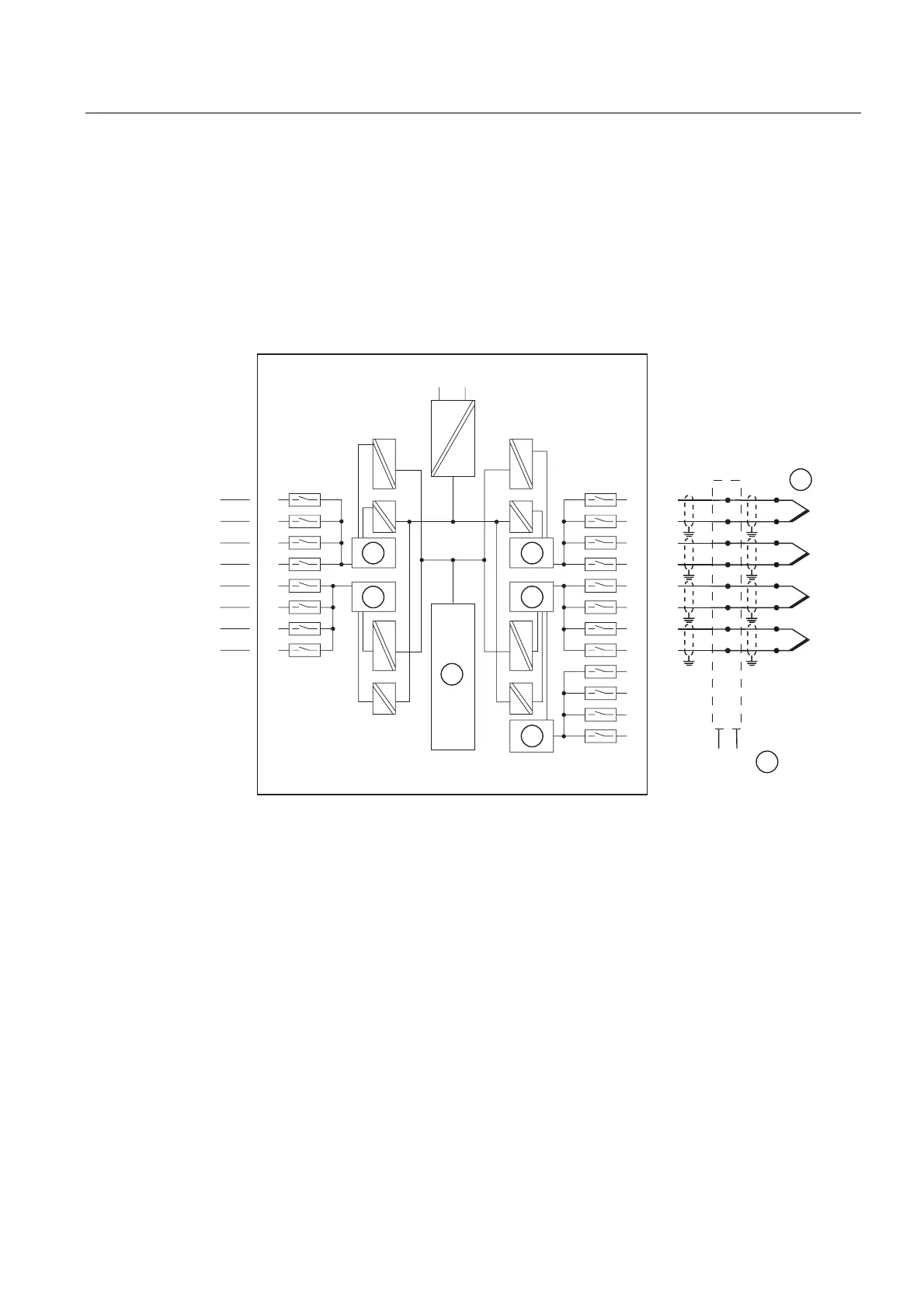
Figure 6-26 Wiring and block diagrams
① Thermocouple via reference junction
② Reference junction regulated to 0 °C or 50 °C
e.g. compensation box (per channel) or thermostat
③ Analog-to-Digital Converter (ADC)
④ Backplane bus interface
⑤ External cold spot comparison
 Loading...


