Analog modules
6.11 Analog output module SM 332; AO 8 x 12 Bit; (6ES7332-5HF00-0AB0)
S7-300 Automation System Module data
Manual, 08/2006, A5E00105505-04
6-101
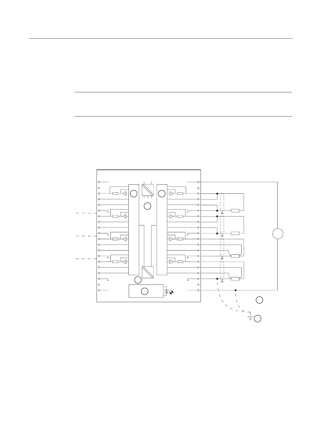
Terminal assignment
The following diagrams show wiring examples. These connection examples apply to all
channels (channel 0 to 7).
Note
When you switch the rated load voltage (L+) off and on, the output may carry incorrect
interim values for the duration of for approx. 10 ms.
Wiring: 2 and 4-wire measuring transducer for current measurement
The following image depicts:
● 2-wire connection, no compensation for line resistors and
● 4-wire connection with compensation for line resistors
/ 0
9
0
0
&+
&+
&+
&+
6)
&+
&+
&+
&+
6
49
6
ದ
0
$1$
6
49
6
ದ
0
$1$
6
49
6
ದ
0
$1$
6
49
6
ದ
0
$1$
9
'&
Figure 6-32 Wiring and block diagrams
Numeral Description
① DAC
② Internal supply
③ Potential compensation
④ Function ground/earth
⑤ Backplane bus interface
⑥ Electrical isolation

 Loading...


