Parameter sets of signal modules
A.10 Parameters of analog output module SM 332; AO 8 x 12 Bit
S7-300 Automation System Module data
Manual, 08/2006, A5E00105505-04
A-39
Note
To enable diagnostic interrupts in the user program at data record 1, you first need to enable
diagnostics at data record 0 in
STEP 7
.
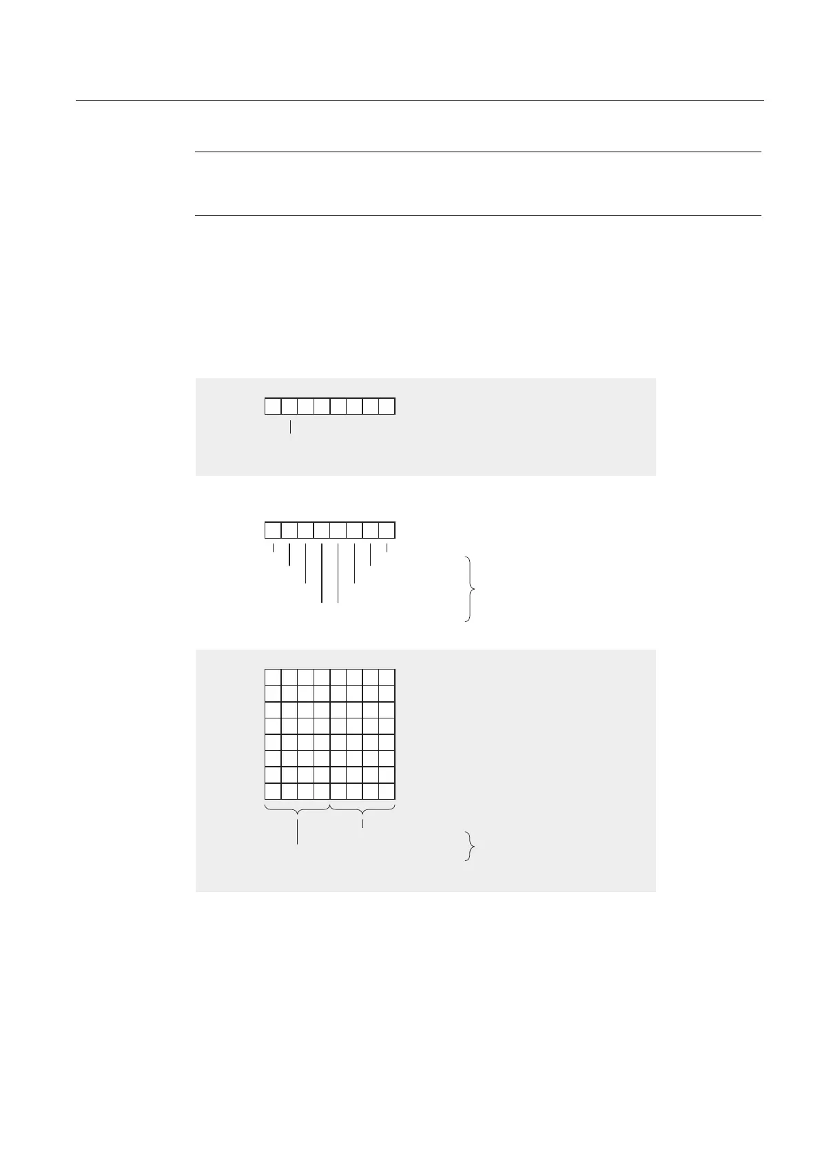
Structure of data record 1
The figure below shows the structure of data record 1 for the parameters of SM 332; AO 8 x
12 Bit.
You enable diagnostics interrupts by setting a logic "1" at the corresponding bit of byte 0.
%\WH
%\WH
%\WH
%\WH
%\WH
%\WH
5HDFWLRQWR&386723
2XWSXWFKDQQHO
2XWSXWFKDQQHO
2XWSXWFKDQQHO
2XWSXWFKDQQHO
%\WH
2XWSXWFKDQQHO
%\WH
2XWSXWFKDQQHO
%\WH
2XWSXWFKDQQHO
%\WH
2XWSXWFKDQQHO
2XWSXWVDW]HUR
FXUUHQWYROWDJH
UHWDLQODVWYDOXH
&KDQQHO
&KDQQHO
&KDQQHO
&KDQQHO
&KDQQHO
&KDQQHO
&KDQQHO
&KDQQHO
6HHFRGHWDEOHIRUWKH
RXWSXWUDQJHVRIWKH
DQDORJRXWSXWPRGXOH
60$2ၮELW
2XWSXWUDQJH
2XWSXWW\SH
'LDJQRVWLFVLQWHUUXSWHQDEOH
%\WHVWRDUHQRWDVVLJQHG
Figure A-21 Data record 1 for the parameters of analog output modules