Parameter sets of signal modules
A.11 Parameters of analog IO modules
S7-300 Automation System Module data
Manual, 08/2006, A5E00105505-04
A-41
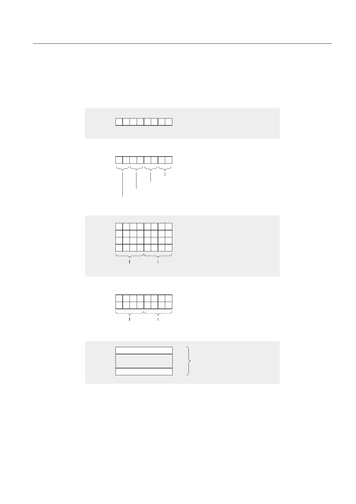
Structure of data record 1
The figure below shows the structure of data record 1 for the parameters of analog IO
modules.
You enable a parameter by setting a logic "1" at the corresponding bit of byte 0.
%\WH
%\WH
%\WH
%\WH
%\WH
%\WH
,QWHJUDWLRQWLPH
0HDVXUHPHQWFKDQQHO
0HDVXUHPHQWFKDQQHO
0HDVXUHPHQWFKDQQHO
0HDVXUHPHQWFKDQQHO
&KDQQHO
&KDQQHO
&KDQQHO
&KDQQHO
0HDVXULQJUDQJH0HDVXULQJPHWKRG
%\WH
%\WH
%\WH
%\WH
2XWSXWFKDQQHO
2XWSXWFKDQQHO
2XWSXWUDQJH2XWSXWW\SH
6HWWKHVDPHSDUDPHWHUVIRU
DOOWKHFKDQQHOV
QRWUHOHYDQW
QRWUHOHYDQW
Figure A-22 Data record 1 for the parameters of analog IO modules

 Loading...


