Digital modules
3.5 How to protect digital modules from inductive overvoltages
S7-300 Automation System Module data
Manual, 08/2006, A5E00105505-04
3-11
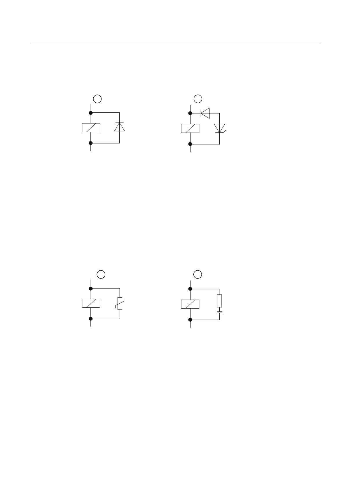
Configuration of coils operated with direct current
Coils operated with direct current are shown in the following diagram and configured with
diodes or Z diodes.
+
-
+
-
Figure 3-2 Configuration of coils operated with direct current
① with diode
② with Z diode
Configuration with diodes/Z diodes has the following characteristics:
● Switching overvoltages can be fully avoided. Z diode has higher transient voltage.
● High cut-out delay (6 to 9 times higher than without protective configuration).
Z diode cuts out faster than with the diode configuration.
Wiring of coils operated with alternating current
Coils operated with alternating current are shown in the diagram and are configured with
varistors or RC elements.
~
~
~
~
Figure 3-3 Wiring of coils operated with alternating current
① with varistor
② with RC element
Configuration with varistor has the following characteristics:
● The amplitude of transient voltage is limited but not damped.
● The steepness of the overvoltage remains the same.
● The cut-out delay is low.
Configuration with RC elements has the following characteristics:
● The amplitude and steepness of the switching overvoltage are reduced.
● The cut-out delay is low.