Digital modules
3.10 Digital input module SM 321; DI 16 x 24 VDC; with hardware and diagnostic interrupts (6ES7321-7BH01-0AB0)
S7-300 Automation System Module data
Manual, 08/2006, A5E00105505-04
3-23
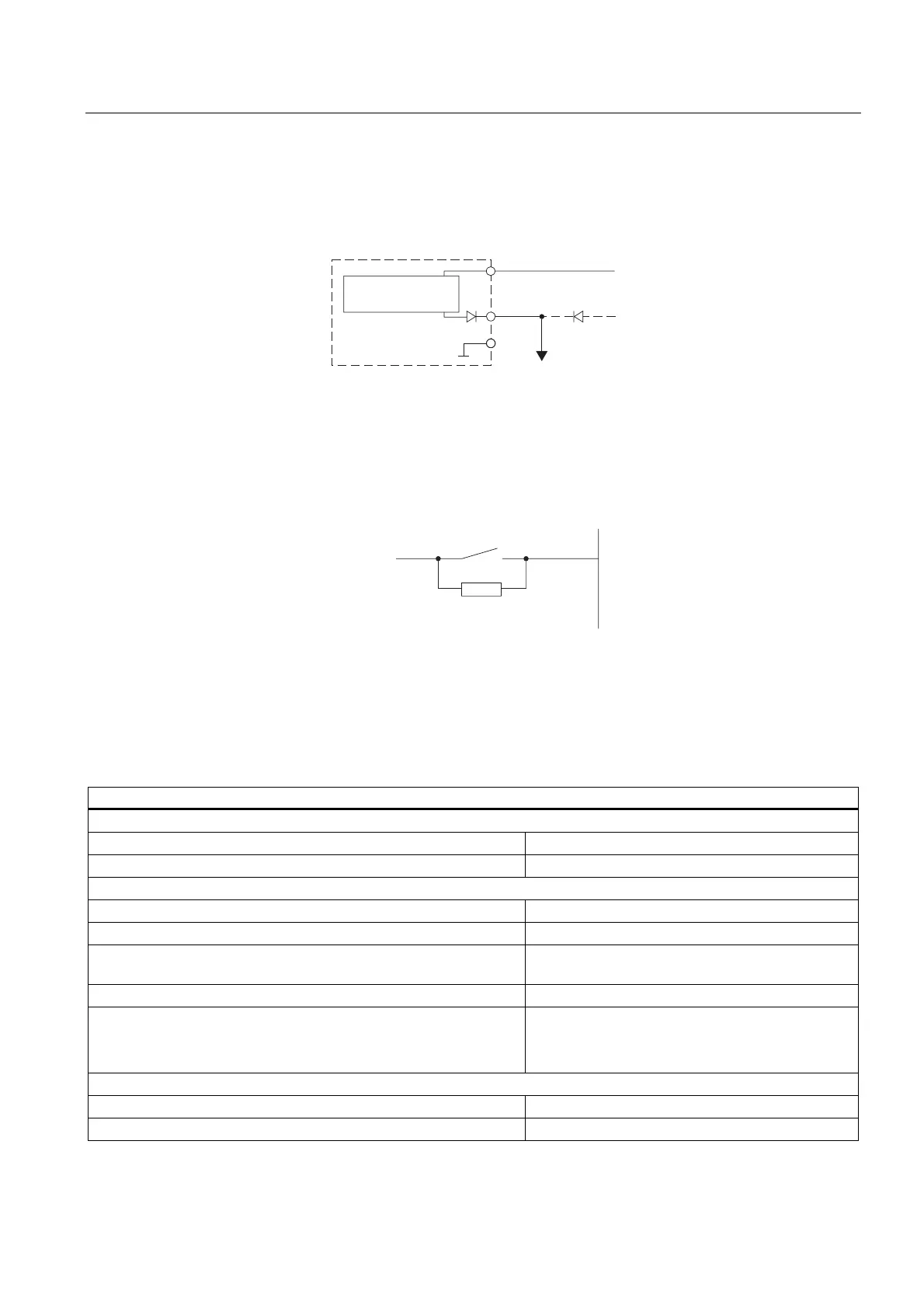
Wiring diagram of the redundant encoder supply
The figure below shows how an additional redundant voltage source can be used to supply
encoders via Vs.
/
/
9V
0
/
6KRUWFLUFXLWSURRI
GULYHU
'LJLWDOLQSXW
PRGXOH
WRWKHHQFRGHUV
Figure 3-4 Wiring diagram of the redundant supply of encoders of SM 321; DI 16 x DC 24 V
Wiring diagram of the shunt circuit of transducers
For wire-break detection, it is necessary to connect a shunt resistor to the transducer
contacts.
([[
/9
V
NN
Figure 3-5 Wiring diagram of the shunt circuit of transducers of SM 321; DI 16 x DC 24 V
Technical data of SM 321; DI 16 x DC 24 V
Technical data
Dimensions and weight
Dimensions W x H x D (mm) 40 x 125 x 117
Weight approx. 200 g
Module-specific data
Isochronous mode supported Yes
Support of CiR Yes
• Reaction of non-programmed inputs
return the process value which was valid before
configuration
Number of inputs 16
Cable length
• unshielded
• shielded
max. 600 m
max. 1000 m
Voltages, currents, electrical potentials
Rated supply voltage L+ for electronics and encoders 24 VDC
• Reverse polarity protection
Yes
 Loading...


