Digital modules
3.32 Digital output module SM 322; DO 8 x AC 120/230 V/2 A ISOL (6ES7322-5FF00-0AB0)
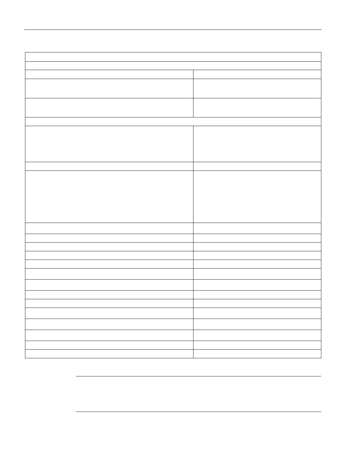
S7-300 Module data
194 Manual, 06/2017, A5E00105505-AJ
Status, interrupts, diagnostics
Status display green LED per channel
Interrupts
• Diagnostic interrupt
programmable
Diagnostic functions
• Group error display
red LED (SF)
Output voltage
• "1" signal
– At maximum current
– At minimum current
min. L1 (-1.5 V)
min L1 (-8.5 V)
• "1" signal
Rated value
permissible range at 0 °C to 40 °C
permissible range at 40 °C to 60 °C
Maximum inrush current (per group)
2 A
10 mA to 2 A
10 mA to 1 A
20 A (with two half-waves)
• "0" signal (residual current)
max. 2 mA
Size of the motor starter
Wiring two outputs in parallel
• for redundant load control
supported
• for performance increase
not supported
Control of a digital input
• with resistive load
max. 10 Hz
• with inductive load to IEC 947-5-1, AC 15
max. 0.5 Hz
• with lamp load
max. 1 Hz
Short circuit-proof output
yes, 3.15 A / 250 V fuse, fast-blow
Using a 40-pin front connector
tputs must be protected by a high-speed, fast-blow 3.15 A 250 V AC fuse. Hazardous
areas to National Electric Code must be determined safe before you remove/replace the
fuse. Removal and replacement may only be possible using a suitable tool.