Analog modules
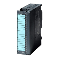
6.16 Analog IO module SM 334; AI 4/AO 2 x 8/8 Bit; (6ES7334-0CE01-0AA0)
S7-300 Module data
Manual, 06/2017, A5E00105505-AJ
481
Input ranges (rated values) / input impedance
• Voltage
• Current
0 V to 10 V/100 k Ω
0 mA to 20 mA/50 Ω
Maximum voltage at voltage input (destruction limit) max. 20 V continuous; 75 V for max. duration of 1 s
Maximum current at current input (destruction limit) 40 mA
Wiring of the signal sensors
• for voltage measurement
• for current measurement
as 2-wire transducer
as 4-wire transducer
using a 20-pin front connector
supported
supported with external
supply
Output ranges (rated values)
• Voltage
• Current
0 V to 10 V
0 mA to 20 mA
Load impedance (in the rated output range)
• For voltage outputs
– capacitive load
• For current outputs
– inductive load
min. 5 kΩ
max. 1 µF
max. 300 Ω
max. 1 mH
Voltage output
• Short-circuit protection
• Short-circuit current
yes
max. 11 mA
Current output
• noload voltage
max. 15 V
Destruction limit against external voltages/currents
• Voltage at outputs to MANA
• Current
max. 15 V, continuous
max. 50 mA d.c.
Wiring of the actuators
• for voltage output
2-wire connection
4-wire connection (measuring line)
using a 20-pin front connector
supported
not supported




 To Next Page
