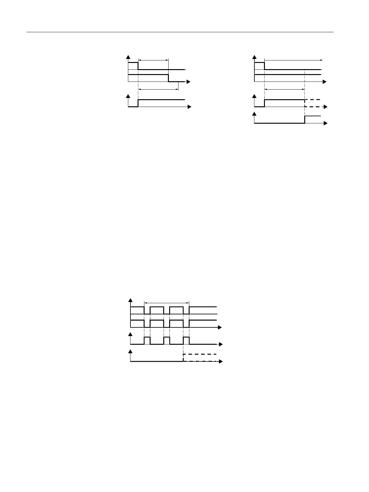
)',LQSXWVLJQDOV
6DIHW\IXQFWLRQ
DFWLYH
6DIHW\IXQFWLRQ
DFWLYH
'LVFUHSDQF\WLPH'LVFUHSDQF\WLPH
'LVFUHSDQF\'LVFUHSDQF\
7HPSRUDU\GLVFUHSDQF\
)',LQSXWVLJQDOV
6LJQDOGLVFUHSDQF\
3HUPDQHQWGLVFUHSDQF\
W
W
W
W
W
Figure 5-13 Simultaneity monitoring with discrepancy time
Filter to suppress short signals
In the following cases, an immediate inverter response to signal changes of the fail-safe digital
inputs is not desirable:
● If a fail-safe digital input of the inverter is interconnected with an electromechanical sensor,
signal changes can occur due to contact bounce.
● In order to identify faults due to short-circuit or cross faults, several control modules test
their fail-safe digital outputs with "bit pattern tests" (bright/dark test). If a fail-safe digital
input of the inverter is interconnected with a fail-safe digital output of an open-loop control
module, then the inverter responds with a bit pattern test.
The typical duration of the signal change within a bit pattern test:
– On test: 1 ms
– Off test: 4 ms
If the fail-safe digital input responds to many signal changes within a certain time, then the
inverter responds with a fault.
)',LQSXWVLJQDOV
6DIHW\IXQFWLRQDFWLYH
)DXOW)
%LWSDWWHUQWHVW
W
W
W
Figure 5-14 Inverter response to a bit pattern test
A filter in the inverter suppresses brief signals as a result of the bit pattern test or contact
bounce.
Commissioning
5.12 Setting extended functions
Safety Integrated - SINAMICS G110M, G120, G120C, G120D and SIMATIC ET 200pro FC-2
160 Function Manual, 01/2017, FW V4.7 SP6, A5E34261271B AD

 Loading...


