5. If the ramp-down time (OFF3) in your application is less than 10 seconds, then leave the
delay time at its factory setting. If SS1 goes into a fault condition during the function test,
increase this value until the motor brakes normally without a fault.
If the ramp-down time (OFF3) is set to several minutes, you must extend the delay time to
several seconds in order to avoid any unwanted faults when selecting SS1.
6. The monitoring time defines the gradient of the monitoring curve when braking the load.
If the monitoring curve should be parallel to the down ramp of the load, then you must set
the following: Monitoring time = ramp-down time (OFF3) / gear ratio.
Gear ratio = load/motor revolutions.
Example: Gear ratio = 1 / 3 ⇒ monitoring time = ramp-down time (OFF3) × 3.
A monitoring time shorter than the above calculated value does not make sense, as the
inverter can reduce its monitoring curve faster than the load can be braked.
The longer you set the monitoring times, the more tolerant the monitoring.
7. Set the reference speed to the value of the maximum speed.
8. Close the screen forms.
You have set the SS1 function with braking ramp monitoring.
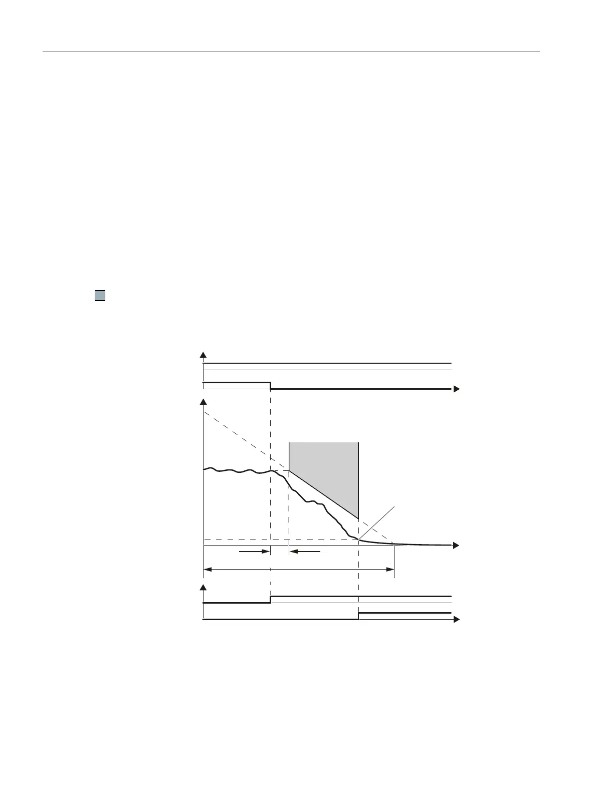
Description: SS1 with braking ramp monitoring
7KHPRWRUFRDVWV
WRDVWDQGVWLOO
0RQLWRULQJWLPH
6SHHG
5HIHUHQFHVSHHG
6KXWGRZQVSHHG
212))
'HVHOHFW66
66DFWLYH
672DFWLYH
'HOD\WLPH
W
W
W
6%5
672
Figure 5-22 SS1 with braking ramp monitoring
Reference speed and monitoring time
The two values define the gradient of the SBR monitoring .
Commissioning
5.12 Setting extended functions
Safety Integrated - SINAMICS G110M, G120, G120C, G120D and SIMATIC ET 200pro FC-2
178 Function Manual, 01/2017, FW V4.7 SP6, A5E34261271B AD

 Loading...


