Description of the SLS function
6SHHG
6SHHGPRQLWRULQJ
6HWSRLQWVSHHGOLPLW
'HVHOHFW6/6
212))
6/6DFWLYH
'HOD\WLPHEUDNLQJUDPSPRQLWRULQJ'HOD\WLPH
6/6VHOHFWൺ6/6DFWLYH
6/6
6%5
W
W
W
6/6
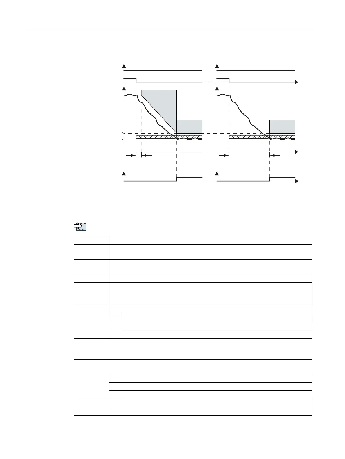
Figure 5-24 Behavior after selecting SLS. Left: with braking ramp monitoring; right: without braking
ramp monitoring
After selecting SLS, the inverter brakes the motor according to the OFF3 ramp-down time.
Setting SS1 with braking ramp monitoring (Page 176)
Parameter Description
p1051 Speed limit RFG positive direction of rotation (Factory setting depends on the Control
Unit)
p1052 Speed limit RFG negative direction of rotation (Factory setting depends on the Control
Unit)
p1135 OFF3 ramp-down time
p9501.00 Enable safety functions
1 signal: Enable SLS and extended functions.
0 signal: Inhibit SLS and extended functions.
p9506 Function specification: (Factory setting: 1)
1: With braking ramp monitoring
3: Without braking ramp monitoring
p9531[0…3] SLS limit values (factory setting for all levels: 2000 rpm)
p9533 SLS setpoint speed limiting (factory setting: 80 %)
The inverter limits the setpoint to the value r9733.
r9733[0] = p9531[x] × p9533.
p9551 SLS changeover delay time (factory setting: 100 ms)
Delay time SLS selection → SLS active, inactive for brake ramp monitoring
p9563[0…3] SLS-specific stop response (Factory setting: STOP A)
0: STOP A
1: STOP B
p9581 Brake ramp reference value (factory setting: 1500 rpm)
Reference speed for SBR
Commissioning
5.12 Setting extended functions
Safety Integrated - SINAMICS G110M, G120, G120C, G120D and SIMATIC ET 200pro FC-2
186 Function Manual, 01/2017, FW V4.7 SP6, A5E34261271B AD

 Loading...


