EasyManuals Logo

Siemens SINUMERIK 840D sl Function Manual

Siemens SINUMERIK 840D sl
2184 pages
To Next Page IconTo Next Page
To Previous Page IconTo Previous Page
Page #1829 background imageLoading...
Page #1829 background image
Detailed Description
2.3 Tool cutting edge
Basic logic functions: Tool Offset (W1)
Function Manual, 11/2006, 6FC5397-0BP10-2BA0
41
Length of cutting edge
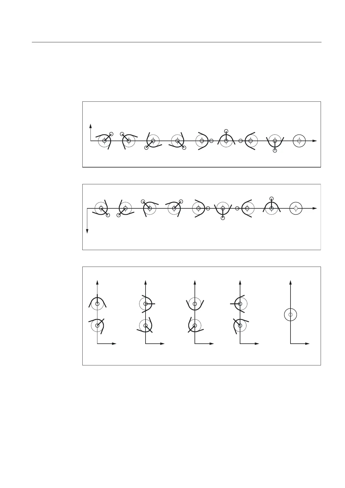
The cutting edge position describes the position of the tool tip P in relation to the cutting
edge center point S. The cutting edge position is entered in tool parameter 2 (shown as P2 in
the figure).
3  3  3 3  3  3  3 
3 6
3 3 
;
=
3
6
Figure 2-6 Tool parameter 2 (P2): Machining behind the turning center
3  3  3 3  3  3  3 
3 6
3 3 
;
=
3
6
Figure 2-7 Tool parameter 2 (P2): Machining in front of the turning center
;
=
3  3 
3 
3  3 
3  3 
3 6
3 
3 
3
6
;
=
;
=
;
=
;
=
Figure 2-8 Tool parameter 2 (P2): Cutting edge position for vertical boring and turning mills

Table of Contents

Other manuals for Siemens SINUMERIK 840D sl

Questions and Answers:

Question and Answer IconNeed help?

Do you have a question about the Siemens SINUMERIK 840D sl and is the answer not in the manual?

Siemens SINUMERIK 840D sl Specifications

General IconGeneral
Control TypeCNC
Number of AxesUp to 31
Max Number of Channels10
InterfacesEthernet, PROFIBUS, PROFINET, USB
Interpolation5-axis interpolation
Operating Temperature0°C to 45°C
Relative HumidityUp to 95% (non-condensing)
DisplayTFT color display, various sizes
Programming LanguagesDIN/ISO
Safety FeaturesSafety Integrated
PLCIntegrated PLC S7-300
Drive InterfaceSINAMICS S120
Data StorageCF card, USB
Operating SystemWindows-based

Related product manuals