Detailed description
2.3 Coordinate systems
Basic logic functions: Axes, coordinate systems, frames (K2)
48 Function Manual, 11/2006, 6FC5397-0BP10-2BA0
*
\
[
]
]
]
\
\
[
[
*
[
\
]
[
\
]
]
\
[
6=6
:&6
%=6
6=6
:&6
0&6
%&6
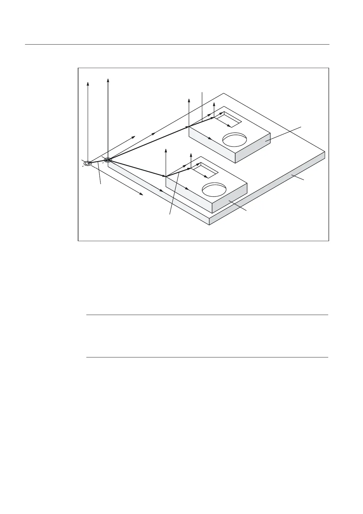
%DVHIUDPH
3URJUDPPDEOH
IUDPH
:RUNSLHFH
:RUNSLHFH
3DOOHW
3URJUDPPDEOH
IUDPH
Figure 2-19 Example of the use of the basic offset
The following settings apply:
• The user can change the basic offset from the part program by means of an operator
action and from the PLC.
• If the basic offset is to take effect immediately, an ASUB can be started via the PLC using
FC9 in order to execute the appropriate G code.
Note
Recommendation to the machine manufacturer
Use the 3rd basic offset onwards for your own applications.
The 1st and 2nd basic offset are reserved for PRESET and the "Zero offset external".

 Loading...


