11.03 3 Safety-Related Functions
3.5 Safely-reduced speed (SG)
© Siemens AG 2003 All Rights Reserved
SINUMERIK 840D/SIMODRIVE 611 digital SINUMERIK Safety Integrated (FBSI) - Edition 11.03
3-103
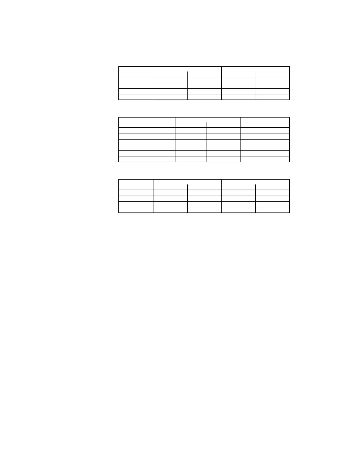
Table 3-28 Supplying MDs for SGEs
For 840D For 611 digital
Limit value MD number Value MD number Value
SG1
36931[0]
1000
1331[0]
1000
SG2
36931[1]
2000
1331[1]
2000
SG3
36931[2]
4000
1331[2]
4000
SG4
36931[3]
5000
1331[3]
5000
Table 3-29 Supplying MDs for SGEs
Signal Assignment
SGE MD number Value Remarks
SG select, bit 1
36972[1]
01 06 04 02
SG select, bit 0
36972[0]
01 06 04 01
SG override selection bit 3
36978
[
3
]
00 00 00 00 Not configured
SG override selection bit 2
36978[2]
00 00 00 00 Not configured
SG override selection bit 1
36978[1]
01 06 04 04
SG override selection bit 0
36978[0]
01 06 04 03
Table 3-30 Supplying MDs for override values
Override For 840D For 611 digital
MD number Value MD number Value
0
36932[0]
100
1332[0]
100
1
36932[1]
80
1332[1]
80
2
36932[2]
50
1332[2]
50
3
36932[3]
30
1332[3]
30
3.5.8 Application examples for SG
Please refer to Chapter 7, "Configuring example" for an example of safely-
reduced speed.
3.5.9 Examples for safe input of ratios
The gear ratio (encoder/load) must be safely sensed on a spindle with a four-
stage gearbox.
Two examples are given, one with a
2-encoder system (ex. 1, refer to Fig. 3-13 Spindle with a 2-encoder system)
and one with a
1-encoder system (ex. 2, refer to Fig 3-14 Spindle with a 1-encoder system).
Example 1: Spindle with a 2-encoder system
The two channels are monitored by comparing the speed sensed by the second
encoder with the speed of the motor encoder, taking the gear ratio into account.
The ratio selection does not have to be safely monitored and only has to
involve one channel.
• The gear stage is selected from an NC program with an H function via the
PLC user program.
Defining machine data
Task assignment
Assumptions for
example 1