11.03 4 Data Descriptions
4.3 Interface signals
© Siemens AG 2003 All Rights Reserved
SINUMERIK 840D/SIMODRIVE 611 digital SINUMERIK Safety Integrated (FBSI) - Edition 11.03
4-255
4.3 Interface signals
The safety-relevant input and output signals (SGEs and SGAs) are signals that
are sent to and received from the system via two channels:
• Via the NCK monitoring channel
<--> NCK I/O devices <--> signal processing <-->
NCK SGE/SGA interface <-> NCK-CPU
• Via the drive monitoring channel
<--> PLC I/O devices <--> signal processing via PLC <-->
NC/PLC interface <-->drive CPU
Note
The SGEs/SGAs in the drive monitoring channel are mapped in an area of
the NC/PLC interface (signals to/from drive) and must be supplied in the PLC
user program.
As a result of the two-channel structure of Safety Integrated, the machine
manufacturer must supply the SGEs and SGAs in both the NCK monitoring
channel and the drive monitoring channel.
Unused SGEs must be set to a defined state.
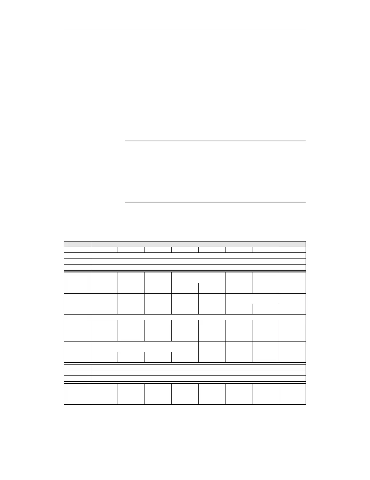
4.3.1 Interface signals for SINUMERIK 840D
Table 4-3 Interface signals for 840D
DB 31... Signals to/from drive
Byte Bit 7 Bit 6 Bit 5 Bit 4 Bit 3 Bit 2 Bit 1 Bit 0
... ...
... ...
... ...
22 Reserved Reserved Reserved SG selection Reserved SBH- SBH/SG-
Bit 1 Bit 0 De-
selection
De-
selection
23 Test stop Reserved Reserved SE- Reserved Gear ratio selection
Selection: Selection Bit 2 Bit 1 Bit 0
SGE (signals to drive)
32 Reserved Reserved De-
selection
ext.
STOP_E
De-
selection
ext.
STOP_D
De-
selection
ext.
STOP_C
De-
selection
ext.
STOP_A
Reserved Reserved
33 SG override selection
Bit 3 Bit 2 Bit 1 Bit 0 Reserved Reserved Reserved Reserved
... ...
... ...
... ...
108 Axis safely
referenced
Reserved Reserved Reserved Reserved "Pulses
cancelled"
status
Reserved SBH/ SG
active
General