3 Safety-Related Functions 11.03
3.10 Safe programable logic (SPL) (840D SW 4.4.18)
© Siemens AG 2003 All Rights Reserved
3-164 SINUMERIK 840D/SIMODRIVE 611 digital SINUMERIK Safety Integrated (FBSI) - Edition 11.03
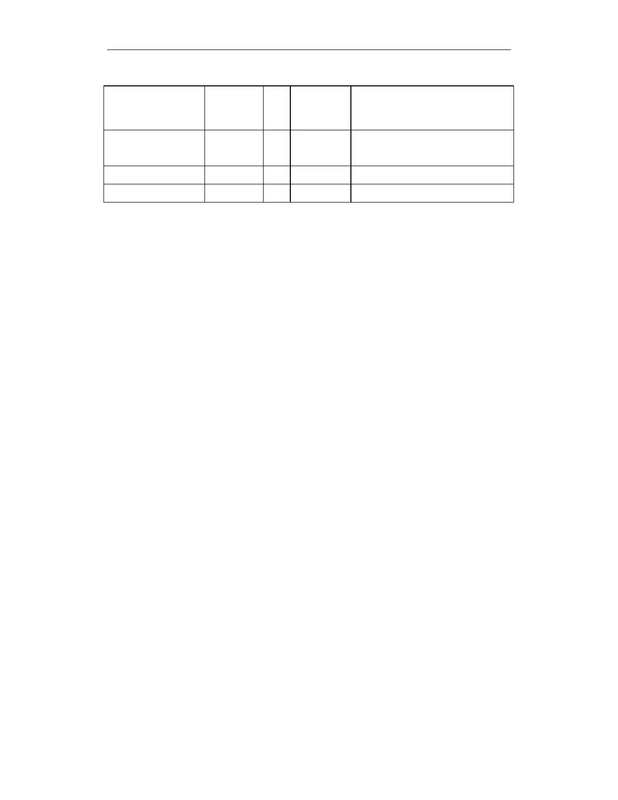
STATSI r Dint 1 - 320 Status: 0 – no error
1 – 320 errors
No. corresponds to signal from SPL_DATA
whose change in level caused the crosswise
data comparison error
LEVELSI r Dint Crosswise data comparison stack level
display
(Diagnostics capability: How many SPL
signals currently have different levels)
PLCSIIN r Bool 1 - 32 Signals can be written by the PLC and read by
the NCK
PLCSIOUT r/w Bool 1 - 32 Signals can be written by the NCK and read
by the NCK
3.10.12 Forced checking procedure of SPL signals
The forced checking procedure of SPL signals is part of the SPL functionality.
Once the external safety circuit has been wired, a two-channel SPL has been
created and the relevant safety functions configured and checked with an
acceptance test, the long-term reliability of this function, verified using an
acceptance test, can be ensured:
• External inputs/outputs
The external inputs/outputs of the SPL ($A_INSE or $A_OUTSE) must be
subject to a forced checking procedure to ensure that faults (e.g. wire
breakage) do not accumulate over a period of time so that both monitoring
channels could fail.
•
Internal inputs/outputs
Internal
inputs/outputs ($A_INSI, $A_OUTSI), markers ($A_MARKERSI)
etc. ($A_TIMERSI) do not have to be subject to a forced checking
procedure. It will always be possible to detect an error at these locations
due to the differing two-channel responses of the external inputs/outputs or
the NCK/611 digital monitoring channels; crosswise data comparison
exists at both ends of the response chain for detecting errors.
"3-terminal concept"
:
• If an input signal ($A_INSE), for example, is evaluated through two
channels, the associated test output signal can be implemented in one
channel
. It is decisive that the input signal can be forced/changed and
checked in both channels.
• In the same way, the assigned test input signal for two-channel output
signals ($A_OUTSE) can be implemented in one channel if it is
interconnected according to the following rules:
The test input signal may only return an "OK" status ("1" level) if both
output signals function (i.e. both monitoring channels have output a "0"). A
simultaneous test
in both channels allows the function to be tested in
both channels using one checkback signal.
SPL signals
Test signals