11.03 3 Safety-Related Functions
3.10 Safe programable logic (SPL) (840D SW 4.4.18)
© Siemens AG 2003 All Rights Reserved
SINUMERIK 840D/SIMODRIVE 611 digital SINUMERIK Safety Integrated (FBSI) - Edition 11.03
3-165
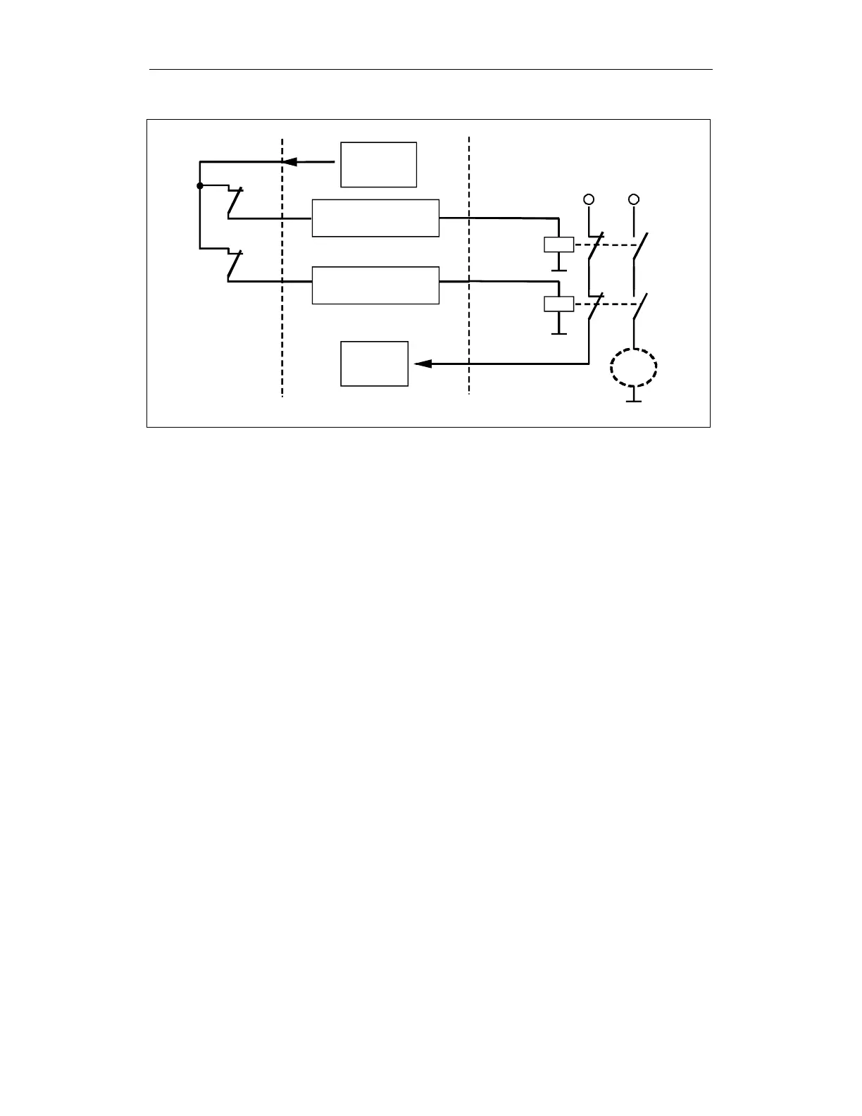
Triggering
PLC-SPL
NCK-SPL
A
A
Test A
E
E
Test E
Test
Load
3KLEMMEN.DSF
Fig. 3-38 3-terminal concept
• The forced checking procedure for the switch evaluated in two channels is
triggered by setting the test output to "0", i.e. actuation of the switch is
simulated.
The NCK-SPL and PLC-SPL must respond to this signal change by setting
their outputs to signal level "0".
• If at least one of the two channels responds in this way, then the load is
disconnected from the power supply.
• Only if both channels respond in this way, will the test input indicate correct
functioning of both channels with level "1". It this is not the case, there is a
system fault and the test analysis ("test" block) must prevent the power
supply being reconnected to the load.
The timer or event controlled triggering of the test stop is activated in one
channel by the PLC. The function itself is separately executed in both channels.
Triggering and checking test signals for SPL input/output signals can also be
completely executed in one channel in the PLC:
1. The PLC is optimized for these types of bit/logic operations and
sequencing logic.
2. The machine adaptation is saved in the PLC user program when
configuring and installing the machine.
If errors are detected, the PLC user program should respond by triggering an
external "STOP D/E".
1. A "2 terminal concept" in which a single-channel useful signal is to be
subjected to a forced checking procedure using a
single-channel test
signal
is
not permitted
. In this case, the two-channel SPL structure would
be worthless and the crosswise data comparison would have no effect.
Explanation of the
diagram
Triggering/test
Notes avoiding errors