3 Safety-Related Functions 11.03
3.11 Encoder mounting arrangements
© Siemens AG 2003 All Rights Reserved
3-168 SINUMERIK 840D/SIMODRIVE 611 digital SINUMERIK Safety Integrated (FBSI) - Edition 11.03
3.11 Encoder mounting arrangements
3.11.1 Encoder types
The following basic types of encoder can be used on a drive module for the
purpose of safe operation:
• Incremental encoder
with sinusoidal voltage signals A and B (signal A is in quadrature with
signal B) and a reference signal R
e.g.: ERN 1387, LS 186, SIZAG2
• Absolute encoder
with EnDat interface and incremental, sinusoidal voltage signals A and B
(signal A is in quadrature with signal B)
e.g.: EQN 1325, LC 181
Various combinations can be derived from the basic types.
Table 3-64 Combinations of encoder types
Incremental encoder Absolute encoder
at the motor at the load at the motor at the load Comments
x 1-encoder system
x 1-encoder system
x x 2-encoder system
x x 2-encoder system
x x 2-encoder system
Note: x Encoder connection
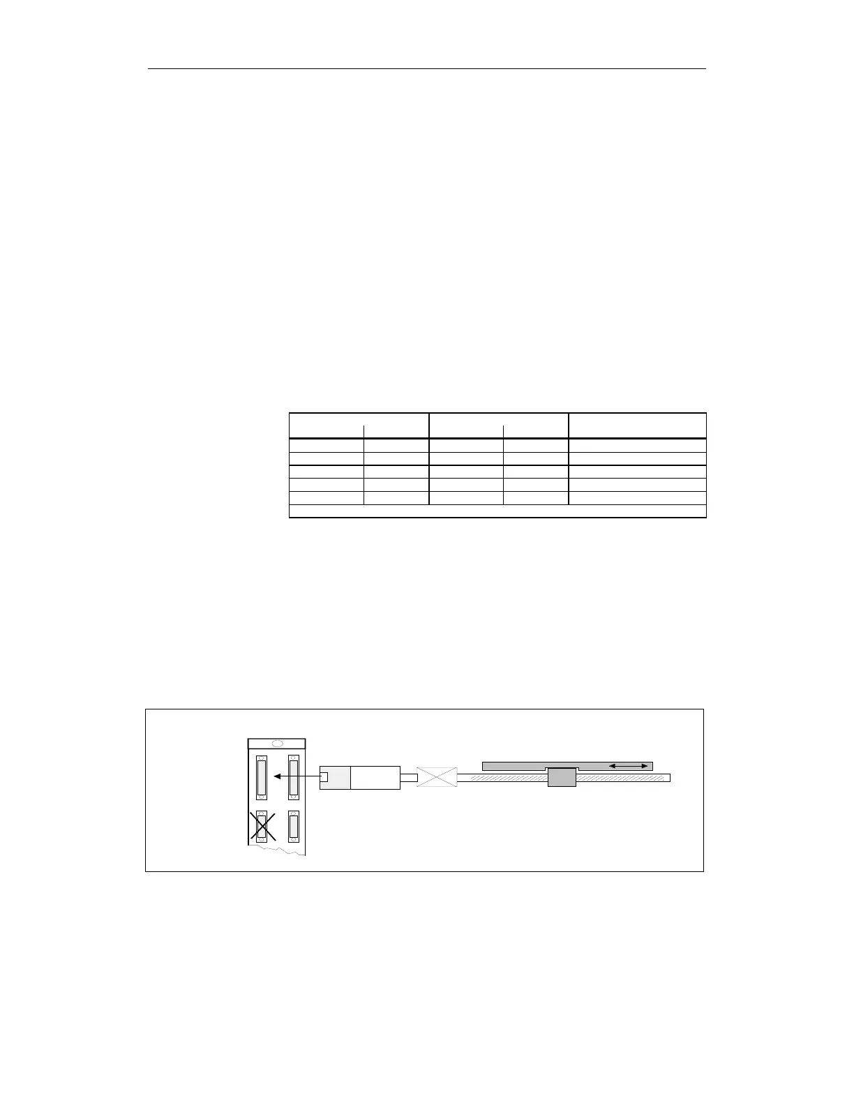
For a 1-encoder system, the incremental or absolute encoder at the motor is
used for the actual values of the NC and drive.
The 611 digital control module supplies one actual value to the NCK and drive
via 2 separate actual value channels..
Special feature for linear motors:
For linear motors, the motor encoder (linear scale) is also the measuring
system at the load. IMS and DMS are one measuring system. The connection
is made at the IMS input of the 611 digital control module.
Geber
Getriebe
Lose
GEBER_02.DSF
Anschluß
des
Motorgebers
(IMS)
Motor
(VSA)
Maschinentisch
VSA
Anschluß
des direkten
Lagegebers
(DM S)
Fig. 3-39 1-encoder system for a feed drive
Basic types
Combinations of
encoder types
1-encoder system