7 Configuring example 11.03
7.6 SI I/Os using fail-safe modules connected to PROFIBUS DP
© Siemens AG 2003 All Rights Reserved
7-428 SINUMERIK 840D/SIMODRIVE 611 digital SINUMERIK Safety Integrated (FBSI) - Edition 11.03
Significance and use of the individual signals:
PM-E F (channel 0) : Valve unit 3
Signal status channel 0 = "0"
Valve in the inhibited/quiescent position
Signal status channel 0 = "1"
Valve open
PM-E F (channel 1) : Not used
PM-E F (channel 2) : Shutting down the supply voltage for subsequent
DO module / external not used
Signal status channel 2 = "0"
The power supply voltage for the subsequent DO module is
disconnected via the two potential rails P1/P2.
Signal status channel 2 = "1"
The power supply voltage for the subsequent DO module is switched-
in via the two potential rails P1/P2.
7.6.3 Individual application functions
The <drive on> button is only used to acknowledge the internal Emergency
Stop state. The button has no function in subsequent operation. The table of
functions below shows the logical inter-relationships between the individual
safety-relevant signals and functions. The description starts with the
assumption that the Emergency Stop state has been acknowledged.
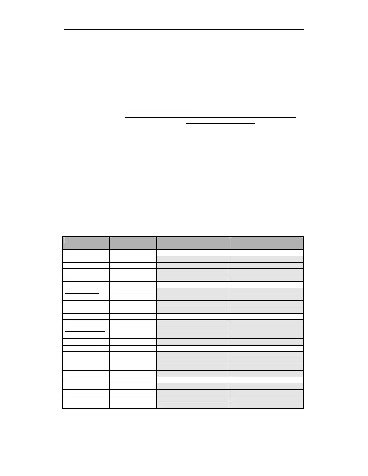
Table 7-1 Application functions
Sensor State Axes, spindles/
external devices
Monitor function/
switching status
Emergency Stop Not actuated Axes/spindles SG3 (> maximum speed)
Protective door Closed Valve unit 1 Open position
Agreement button Not applicable Valve unit 2 Open position
Valve unit 3 Open position
Case 1 Supply voltage DO Connected
Emergency Stop Not actuated Axes/spindles SBH
Protective door Open Valve unit 1 Inhibit-quiescent position
Agreement button Not pressed Valve unit 2 Inhibit-quiescent position
Valve unit 3 Inhibit-quiescent position
Case 2
Supply voltage DO Disconnected
Emergency Stop Not actuated Axes/spindles SG1
Protective door Open Valve unit 1 Open position
Agreement button Pressed Valve unit 2 Inhibit-quiescent position
Valve unit 3 Open position
Case 3 Supply voltage DO Disconnected
Emergency Stop Actuated Axes/spindles STOP C -> SBH
Protective door Open Valve unit 1 Inhibit-quiescent position
Agreement button Pressed Valve unit 2 Inhibit-quiescent position
Valve unit 3 Inhibit-quiescent position
Case 4
Supply voltage DO Disconnected
Emergency Stop Actuated Axes/spindles STOP D -> SBH
Protective door Closed Valve unit 1 Inhibit-quiescent position
Agreement button Pressed Valve unit 2 Inhibit-quiescent position
Valve unit 3 Inhibit-quiescent position
Case 5 Supply voltage DO Disconnected