11.03 3 Safety-Related Functions
3.6 Safe software limit switches (SE)
© Siemens AG 2003 All Rights Reserved
SINUMERIK 840D/SIMODRIVE 611 digital SINUMERIK Safety Integrated (FBSI) - Edition 11.03
3-113
n
n
act
a) Axis crosses limit position
SE_01.DSF
t
t
6
t
3
t
4
t
2
t
1
t
5
not to scale
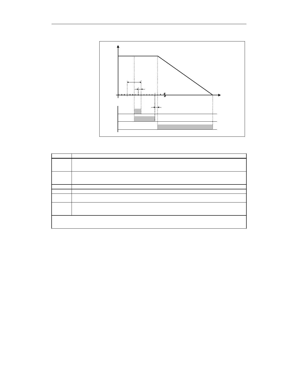
Fig. 3-19 Timing when the software limit switch is passed
Table 3-42 Explanations of the diagram
Time Explanation
t
1
Position control clock cycle defined by the following MDs:
For 840D: MD 10050: $MN_SYSCLOCK_CYCLE_TIME
MD 10060: $MN_POSCTRL_SYSCLOCK_TIME_RATIO
t
2
Monitoring clock cycle defined by the following MDs:
For 840D: MD 10090: $MN_SAFETY_SYSCLOCK_TIME_RATIO
For 611 digital: MD1300: $MD_SAFETY_CYCLE_TIME
t
3
Time until passing limit position is detected (maximum 1 monitoring clock cycle)
t
4
Delay until the configured stop response is output (maximum 2 monitoring clock cycles)
t
5
Delay until the configured stop response takes effect (time = 0, depends on the configured stop response,
refer to Chapter 2, "Stop responses")
t
6
Time required to bring the axis to standstill.
This time period and thus the residual distance traveled by the axis is determined by the axis design
(motor, mass, friction, ...) and the configured stop response (STOP C is faster than STOP D).
Note:
Each axis must be measured during commissioning to determine the distance it travels between the limit value being
violated and it coming to a standstill.