11.03 3 Safety-Related Functions
3.9 Safety-related input/output signals (SGE/SGA)
© Siemens AG 2003 All Rights Reserved
SINUMERIK 840D/SIMODRIVE 611 digital SINUMERIK Safety Integrated (FBSI) - Edition 11.03
3-129
Process User
System
Machine
NCK
HW
I/O
I/O images
Processing
SGE
SGA
NCK
monitoring channel
SBH/SG
SE
SN
per axis/spindle
I1
I_Fig1
SGE ...
Multiple
distribution
...
I2
I_Fig2
SGE ...
In
...
I_Fign
...
SGE ...
O1
O_Fig1
SGA ...
Multiple
assignment
...
O2
O_Fig2
SGA ...
On
...
O_Fign
...
SGA...
I1
I_Fig1
SGE ...
PLC
user
program
...
I2
I_Fig2
SGE ...
In
...
I_Fign
...
SGE ...
O1
O_Fig1
SGA ...
...
O2
O_Fig2
SGA ...
On
...
O_Fign
SGA...
SBH/SG
SE
SN
per axis/spindle
PLC
HW
I/O
I/O images
Processing
SGE
SGA
Drive monitoring channel
PLC
user
program
Monitoring
comparators
Result and data
cross-check
SGESGA01.DS4
Monitoring
comparators
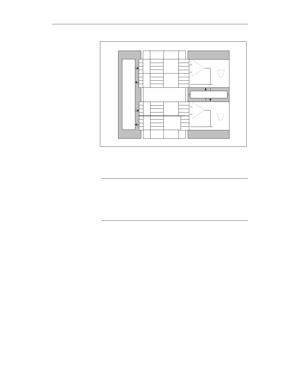
Fig. 3-28 Two-channel processing of I/O signals
The data and results in the two mutually independent monitoring channels are
subject to a crosswise data comparison. If any discrepancy is found, STOP F is
activated.
Note
Owing to the two-channel structure of Safety Integrated, the machine
manufacturer must supply the SGEs and SGAs in both the NCK monitoring
channel and the drive monitoring channel.
The actual signal status of the SGEs/SGAs is selected via the menu "Service
display". The "Service SI" window displays information about Safety
Integrated data together with the associated axis name and axis number.
For a two-channel control structure, only a single-channel signal feedback via
the PLC is needed.
In contrast, when a single-channel control structure is used, a redundant, i.e. a
two-channel feedback structure is required.
The following SGEs and SGAs are provided for each axis/spindle in each of the
two monitoring channels:
Basic principle of safe
signal processing
What SGEs/SGAs are
there?