4 Data Descriptions 11.03
4.1 Machine data
© Siemens AG 2003 All Rights Reserved
4-224 SINUMERIK 840D/SIMODRIVE 611 digital SINUMERIK Safety Integrated (FBSI) - Edition 11.03
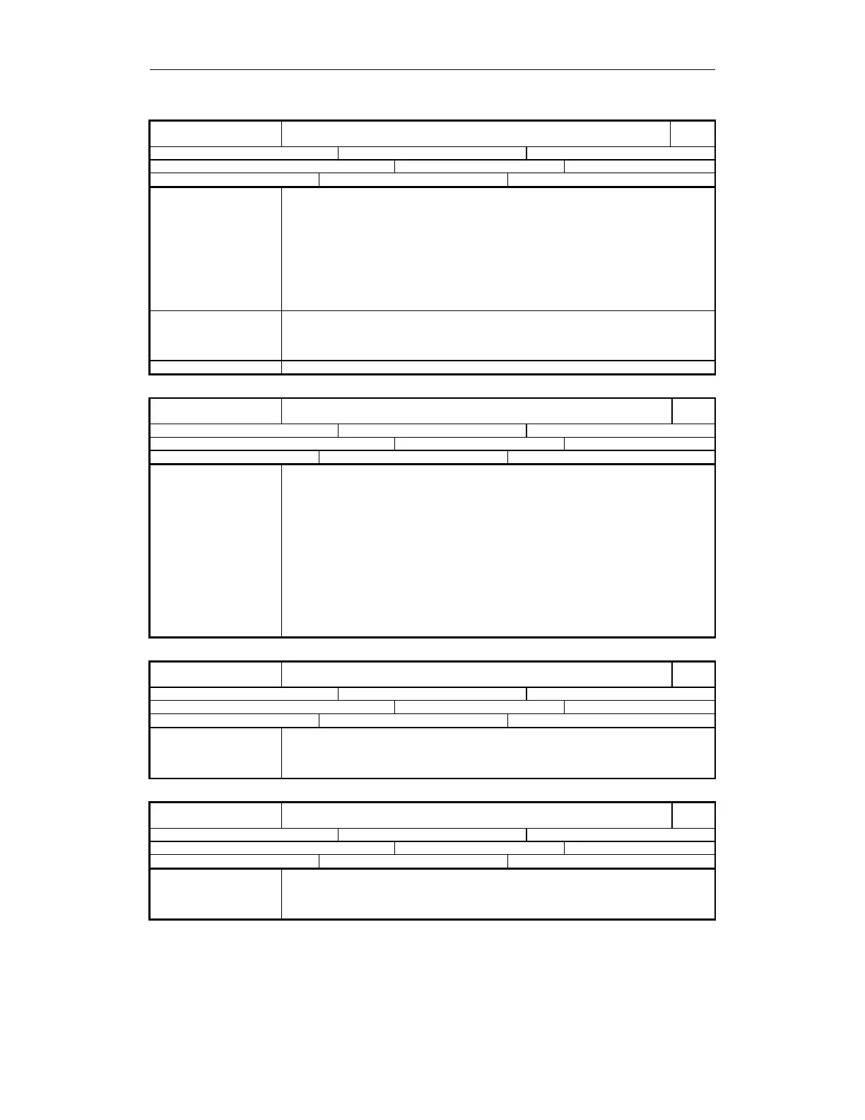
36950
MD number
$MA_SAFE_MODE_SWITCH_TIME
Tolerance time for SGE changeover
840D
Default: 0.5 Min. input value: 0 Max. input value: 10
Change becomes effective after POWER ON: Protection level (R/W) 7/2 Unit: s
Data type: DOUBLE Applies from SW 3.4
Meaning SGE changeovers do not take effect simultaneously owing to variations in run times for
SGE transmission in the two monitoring channels. A crosswise data comparison would
output an error message in this case.
This data is used to specify the period of time after SGE changeover during which no
crosswise comparison of actual values and monitoring results is carried out (machine data
is still compared!). The selected monitoring functions continue to operate unhindered in
both monitoring channels.
A safe function is immediately activated in a monitoring channel if selection or changeover
is detected in this channel.
The different run times are mainly determined by the PLC cycle time.
Special cases, errors System-dependent minimum tolerance time:
2 x PLC cycle time (maximum cycle) + 1 x IPO cycle time
The variations in run times in the external circuitry (e.g. relay operating times) must also
be taken into account.
References Refer to Chapter 3, "Safety-relevant input/output signals (SGE/SGA)"
36951
MD number
$MA_SAFE_VELO_SWITCH_DELAY
Delay time speed changeover
840D
Default: 0.1 Min. input value: 0 Max. input value: 10
Change becomes effective after POWER ON: Protection level (R/W) 7/2 Unit: s
Data type: DOUBLE Applies from SW 3.4
Meaning A timer with the value in this data is started when changing from a high to a lower safely-
reduced speed or when a safe operating stop is selected when the safely-reduced speed
function is active.
While the timer is running, the speed continues to be monitored for the last selected
speed limit value. During this period, the axis/spindle can be braked, for example, via the
PLC user program without the monitoring function signaling an error and initiating a stop
response.
Examples:
1. The timer is interrupted as soon as a higher or identical SG limit (i.e. to that which
was previously active) is selected.
2. The timer is interrupted if "non-safe operation" (=NSB SGE "de-select SBH/SG=1) is
selected.
3. The timer is retriggered (restarted) if an SG limit lower than the one previously active
is selected or SBH is selected while the timer is running.
36952
MD number
$MA_SAFE_STOP_SWITCH_TIME_C
Transition time, STOP C to safe operating stop
840D
Default: 0.1 Min. input value: 0 Max. input value: 10
Change becomes effective after POWER ON: Protection level (R/W) 7/2 Unit: s
Data type: DOUBLE Applies from SW 3.4
Meaning This data defines the time period between the initiation of a STOP C and the activation of
the safe operating stop function.
Once the time has expired, the drive is monitored for safe operating stop. If the
axis/spindle has still not been stopped, STOP B/A is initiated.
36953
MD number
$MA_SAFE_STOP_SWITCH_TIME_D
Transition time, STOP D to safe operating stop
840D
Default: 0.1 Min. input value: 0 Max. input value: 60
Change becomes effective after POWER ON: Protection level (R/W) 7/2 Unit: s
Data type: DOUBLE Applies from SW 3.4
Meaning This data defines the time period between the initiation of a STOP D and the activation of
the safe operating stop function.
Once the time has expired, the drive is monitored for safe operating stop. If the
axis/spindle has still not been stopped, STOP B/A is initiated.