11.03 4 Data Descriptions
4.1 Machine data
© Siemens AG 2003 All Rights Reserved
SINUMERIK 840D/SIMODRIVE 611 digital SINUMERIK Safety Integrated (FBSI) - Edition 11.03
4-231
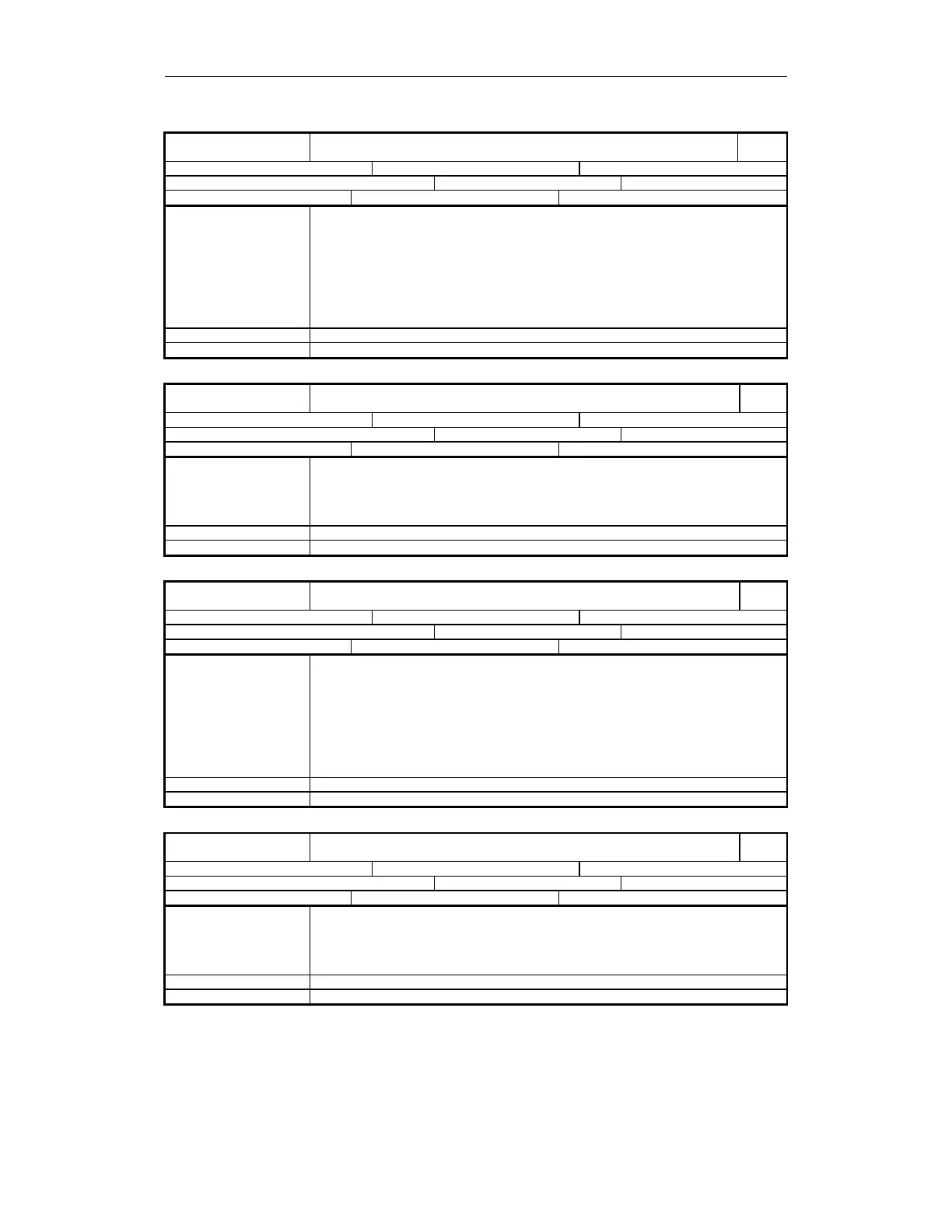
36972
MD number
$MA_SAFE_VELO_SELECT_INPUT[n]
Input assignment, SG selection
840D
Default: 0 Min. input value: 0 Max. input value: -
Change becomes effective after POWER ON: Protection level (R/W) 7/2 Unit: -
Data type: DWORD Applies from SW 3.4
Meaning This data defines the two inputs for selecting SG1, SG2, SG3 or SG4.
Structure: Refer to coding of input assignment
n = 1, 0 stands for bits 1, 0 for selecting SG1 to SG4
Assignment of input bits to safely-reduced speeds:
Bit 1 Bit 0 Selected SG
0 0 SG1
0 1 SG2
1 0 SG3
1 1 SG4
Special cases, errors If the MD bits 31 are set, then the signal is processed inverted (ss = 81).
References MD 36971: $MA_SAFE_SVSS_DISABLE_INPUT
36973
MD number
$MA_SAFE_POS_SELECT_INPUT
Input assignment, SE selection
840D
Default: 0 Min. input value: 0 Max. input value: -
Change becomes effective after POWER ON: Protection level (R/W) 7/2 Unit: -
Data type: DWORD Applies from SW 3.4
Meaning This data defines the input for selecting safe limit position 1 or 2.
Structure: Refer to coding of input assignment
Signal means
= 0 SE1 is active
= 1 SE2 is active
Special cases, errors If MD bit 31 is set, then the signal is processed inverted (ss = 81)
References MD 36970: $MA_SAFE_SVSS_DISABLE_INPUT
36974
MD number
$MA_SAFE_GEAR_SELECT_INPUT[n]
Input assignment, gear ratio selection
840D
Default: 0 Min. input value: 0 Max. input value: -
Change becomes effective after POWER ON: Protection level (R/W) 7/2 Unit: -
Data type: DWORD Applies from SW 3.4
Meaning Assignment of the input terminals for selecting the gear ratio (gear stage).
Structure: Refer to coding of input assignment
n = 2, 1, 0 stands for bits 2, 1, 0 for selecting gear stages 1 to 8
Bit 2 Bit 1 Bit 0 Active gear stage
0 0 0 Stage 1
0 0 1 Stage 2
0 1 0 Stage 3
... ... ... ...
1 1 1 Stage 8
Special cases, errors If the MD bits 31 are set, then the signal is processed inverted (ss = 81).
References MD 36970: $MA_SAFE_SVSS_DISABLE_INPUT
36975
MD number
$MA_SAFE_STOP_REQUEST_INPUT
Input assignment, "test stop selection"
840D
Default: 0 Min. input value: 0 Max. input value: -
Change becomes effective after POWER ON: Protection level (R/W) 7/2 Unit: -
Data type: DWORD Applies from SW 3.4
Meaning This data defines the input for selecting the test stop.
Structure: Refer to coding of input assignment
Signal means
= 0 Test stop is de-activated
= 1 Test stop is executed
Special cases, errors If MD bit 31 is set, then the signal is processed inverted (ss = 81)
References MD 36970: $MA_SAFE_SVSS_DISABLE_INPUT