11.03 8 Application examples
8.2 Two-channel brake control with SI (SPL)
© Siemens AG 2003 All Rights Reserved
SINUMERIK 840D/SIMODRIVE 611 digital SINUMERIK Safety Integrated (FBSI) - Edition 11.03
8-449
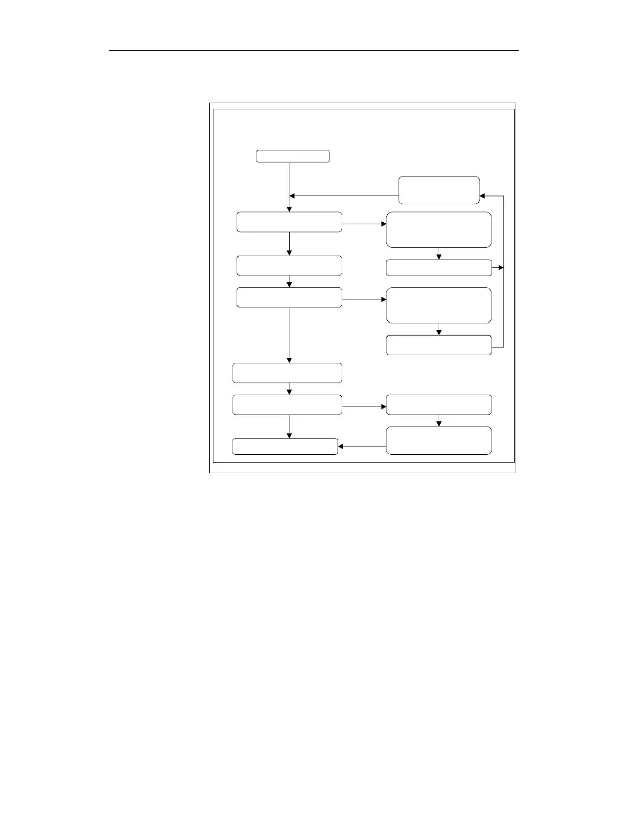
Start of test phase
Check test input I1
(time t )
2
Activate output Q1
(time t )
3
Delayed activation of
output Q2 (time t )
5
Output Q2 no longer capable of
operation after test.
End of test phase
Conductor D1 short-circuit to
current source or switching
element Q1 short-circuit to
current source or malfunction.
Test input: level low
Test input:
level high
Check test input I1
(time t )
4
Test input: level high
Conductor D2 short-circuit to
current source or switching
element Q2 short-circuit to
current source or malfunction.
Test input:
level low
Check test input I1
(time t )
6
Test input: level low
Test input:
level high
Error message
Error message / deactivate
output Q1
Error message / deactivate
output Q1/Q2
Delayed pulse disable
New test?
Brake has already been
applied at this point
(e.g. test stop phase 1)
Fig. 8-4 Flowchart for the test routine
With this safe brake control, only the operating brake represents a potential
hazard.
Description