11.03 8 Application examples
8.6 Direction detection when retracting from SE
© Siemens AG 2003 All Rights Reserved
SINUMERIK 840D/SIMODRIVE 611 digital SINUMERIK Safety Integrated (FBSI) - Edition 11.03
8-467
Fig. 7-40 illustrates the inter-relationships at the machine and is used to explain
the appropriate configuring.
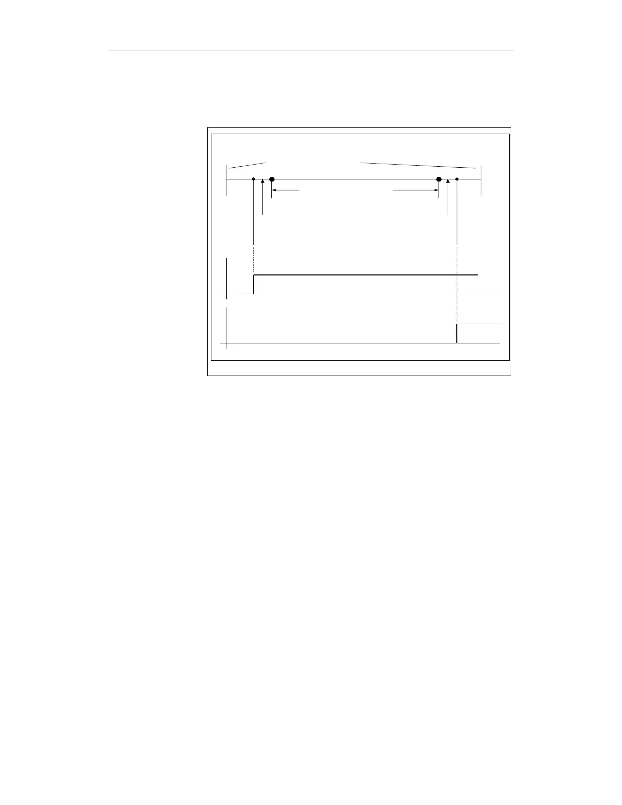
SEFR_00.DSF
Cam signal (SGA)
SNx +
Mechanical traversing limit
SE- SE+
SNx - SNx +
Software limit switch - Software limit switch +
Traversing limits / monitoring
Cam signal (SGA)
SNx -
Traversing area (program)
Fig. 8-11 Example of retraction logic
The minus cam of a cam pair, for example (cams SN1+ - SN4 can all be used),
is set up in the machine data at the position immediately in front of the left safe
limit position (SE-). It must be ensured that SN- is passed if SE- is passed. This
means that the difference should be kept as low as possible (we recommend
0...0.1 mm).
A cam should be set up in the MD at the position directly behind the right safe
limit position.
The signal characteristics (of the interface signals – SGA) for the two
configured cams is shown in the diagram. These two signals can be used to
supply information to the hardware limit switch +/- interface signals.