11.03 3 Safety-Related Functions
3.1 Basic mechanisms of SI functions
© Siemens AG 2003 All Rights Reserved
SINUMERIK 840D/SIMODRIVE 611 digital SINUMERIK Safety Integrated (FBSI) - Edition 11.03
3-71
Note
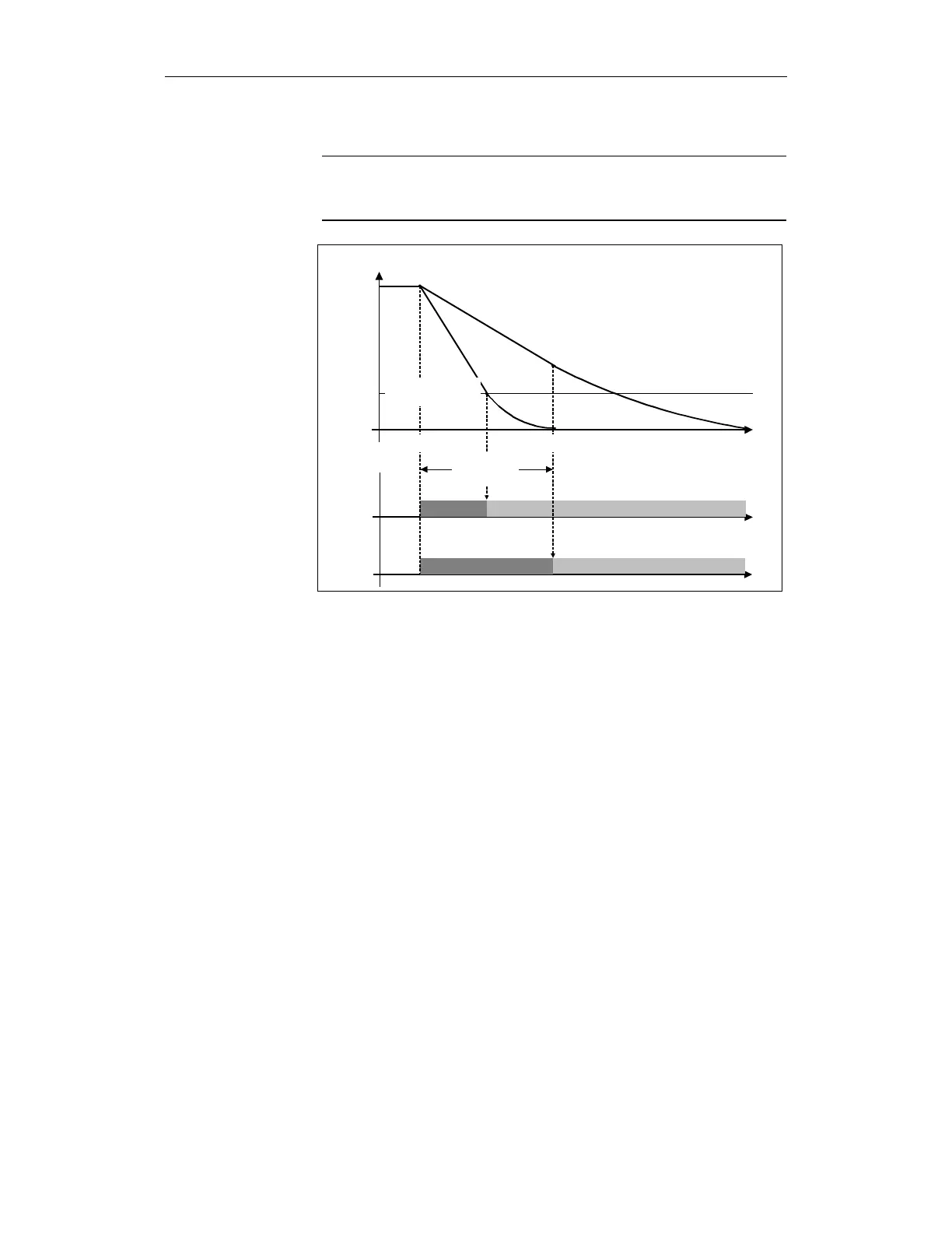
If the timer in machine data $MA_SAFE_PULSE_DISABLE_DELAY is set to
zero, then there is an immediate transition from STOP B to STOP A.
rev/min
a)
b)
Delay time
STOP B
STOP A
STOP A
STOP B
t
STOPB_01.DS4
Creep speed
pulse disabling
STOP B
STOP A
n
ist
a) Creep speed pulse disabling
Delay time pulse disabling
b) Creep speed is reached before
delay time for pulse disabling expires
a)
b)
pulse disabling
Fig. 3-8 Transition from STOP B to STOP A
Action in the drive monitoring channel:
The drive is braked along the current limit in response to a zero speed setpoint
while the timer set in $MD_SAFE_STOP_SWITCH_TIME_C is started in
parallel. The SBH function is automatically activated after the timer expires.
Action in the drive monitoring channel:
Essentially the same as in the drive channel, the control specifies a zero speed
setpoint and interface signal "position controller active" (DB 0, ... DBX 61.5) of
the drive involved is set to zero.
At the same time, the timer set in $MA_SAFE_STOP_SWITCH_TIME_C is
started. The SBH function is automatically activated after the timer expires.
• Effect:
The drive is braked along the current limit under speed control and brought
into SBH.
• Alarm message:
The alarm message "STOP C triggered" is displayed (refer to Chapter 6,
"Alarms").
• Acknowledgement:
An unintentional restart is prevented for STOP C. The error can be
acknowledged using the NC-RESET key.
SGA STOP C is active
This signal indicates that STOP C is active.
0 signal: STOP C is not active
1 signal: STOP C is active
Description of STOP C