Detailed Description
2.4 Protection zones
Axis Monitoring, Protection Zones (A3)
2-34 Function Manual, 08/2005 Edition, 6FC5397-0BP10-0BA0
Definition beginning
The definition start is defined by the corresponding subroutine:
• CPROTDEF(n, t, applim, appplus, appminus)
• NPROTDEF(n, t, applim, appplus, appminus)
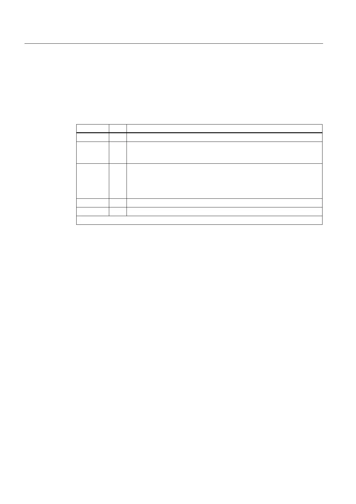
Parameters Type Description
n INT
Number of the defined protection zone
t BOOL
Tool-related protection zone
TRUE: Tool-related protection zone
FALSE: Workpiece-related protection zone
applim INT
Type of limitation in the third dimension
0: No limit
1: Limit in positive direction
2: Limit in negative direction
3: Limit in positive and negative direction
appminus REAL
Value of the limit in the negative direction in the 3rd dimension
1)
appplus REAL
Value of the limit in the negative direction in the 3rd dimension
1)
1) The following must be true: appplus > appminus
Contour description for protection zone
The contour of a protection zone is described with traversing motions. These are not
executed and have no connection to previous or subsequent geometry descriptions. They
only define the protection zone.
The contour of a protection zones is specified with up to eleven traversing movements in the
selected working plane. The first traversing movement is the movement to the contour. The
last point in the contour description must always coincide with the first point of the contour
description. In the case of rotationsymmetrical contours (e.g. spindle chuck), the whole
contour must be described (not merely the contour to the turning center).
The valid protection zone is the zone left of the contour.
• Internal protection zone
The contour of an internal protection zone must described in the counterclockwise
direction.
• External protection zones (permitted only for workpiece-related protection zones)
The contour of an external protection zone must be described in the clockwise direction.
 Loading...


