Detailed Description
2.4 Protection zones
Axis Monitoring, Protection Zones (A3)
Function Manual, 08/2005 Edition, 6FC5397-0BP10-0BA0
2-35
;
;
0
=
3
:
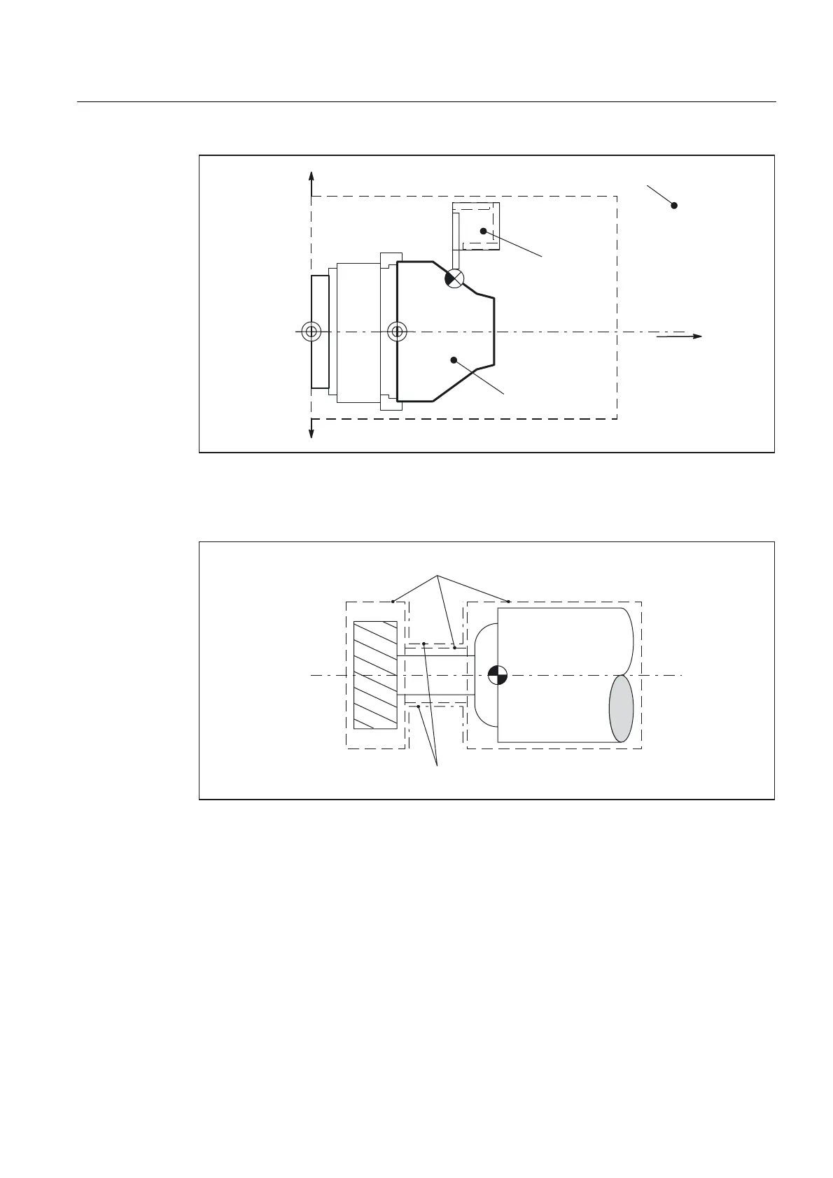
([WHUQDOSURWHFWLRQ]RQH
,QWHUQDOSURWHFWLRQ]RQH
,QWHUQDOSURWHFWLRQ
]RQH
Fig. 2-13 Examples: External and internal protection zone
Toolrelated protection zones must be convex. If a concave protection zone is required, the
protection zone must be divided up into several convex protection zones.
)
&RQYH[SURWHFWLRQ]RQHV
&RQFDYHSURWHFWLRQ]RQHVQRWSHUPLVVLEOH
Fig. 2-14 Examples: Convex and concave tool-related protection zones
Contour elements
The following contour elements are permissible:
• G0, G1 for straight contour elements
• G2 for circle segments in the clockwise direction
Permissible only for workpiece-related protection zones.
Not permissible for tool-related protection zones because they must be convex.
• G3 for circular segments in the counterclockwise direction
 Loading...


