Detailed Description
2.4 Tool: Tool radius compensation 2D (TRC)
Tool Compensation (W1)
Function Manual, 08/2005 Edition, 6FC5397-0BP10-0BA0
2-51
• Programming the end point P
4
(or P
0
for retraction) generally with X... Y... Z....
1. Possible programming of end point P4 for approach:
End point P
4
can be programmed in the actual SAR block.
P
4
can be determined by the end point of the next traversing block.
Further blocks (dummy blocks) can be inserted between the SAR block and the next traversing block
without moving the geometry axes.
The end point is deemed to have been programmed in the actual SAR block for approach if at least
one geometry axis is programmed on the machining plane (X or Y with G17). If only the position of
the axis perpendicular to the machining plane (Z with G17) is programmed in the SAR block, this
component is taken from the SAR block, but the position in the plane is taken from the following
block. In this case, an alarm is output if the axis perpendicular to the machining plane is also
programmed in the following block.
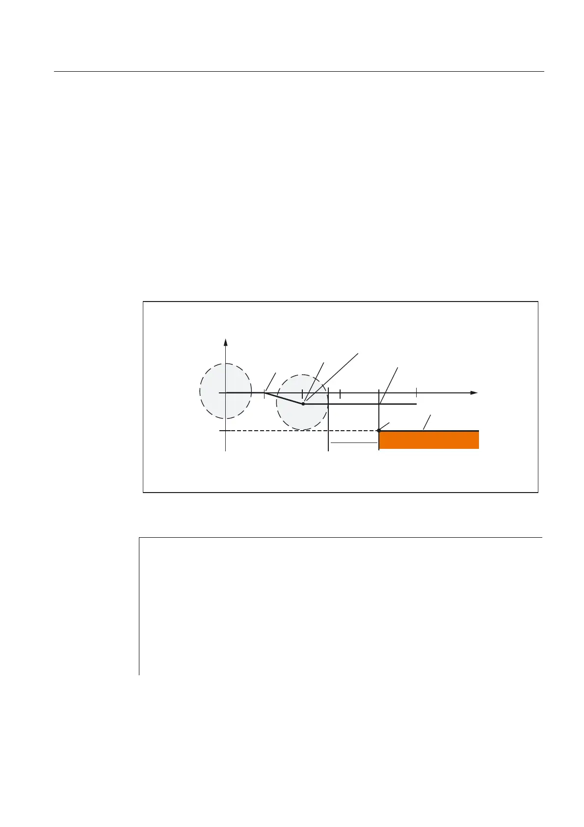
Example:
&RQWRXU
0DFKLQLQJXSWRWKLV
SRLQWZLWK*WKHQZLWK
*)
]
=
=
',65
;
3
<
$TC_DP1[1,1]=120 ; Milling tool T1/D1
$TC_DP6 [1,1] = 7 ; Tool with 7 mm radius
N10 G90 G0 X0 Y0 Z30 D1 T1
N20 X10
N30 G41 G147 DISCL=3 DISR=13 Z=0 F1000
N40 G1 X40 Y-10
N50 G1 X50
...
...
 Loading...


