Detailed Description
2.4 Tool: Tool radius compensation 2D (TRC)
Tool Compensation (W1)
2-52 Function Manual, 08/2005 Edition, 6FC5397-0BP10-0BA0
N30/N40 can be replaced by:
N30 G41 G147 DISCL=3 DISR=13 X40 Y-10 Z0 F1000
or:
N30 G41 G147 DISCL=3 DISR=13 F1000
N40 G1 X40 Y-10 Z0
2. Possible programming of end point P0 for retraction:
The end position is always taken from the SAR block, no matter how many axes have been
programmed. We distinguish between the following situations:
1 No geometry axis is programmed in the SAR block.
In this case, the contour ends at point P
2
(or at point P
1
, if P
1
and P
2
coincide). The position in
the axes, which describe the machining plane, is determined by the retraction contour (end
point of the straight line or arc). The axis component perpendicular to this is defined by DISCL.
If, in this case, DISCL = 0, the movement takes place completely within the plane.
2 Only the axis perpendicular to the machining plane is programmed in the SAR block.
In this case, the contour ends at point P
1
. The position of the two other axes is determined in
the same way as in 1.
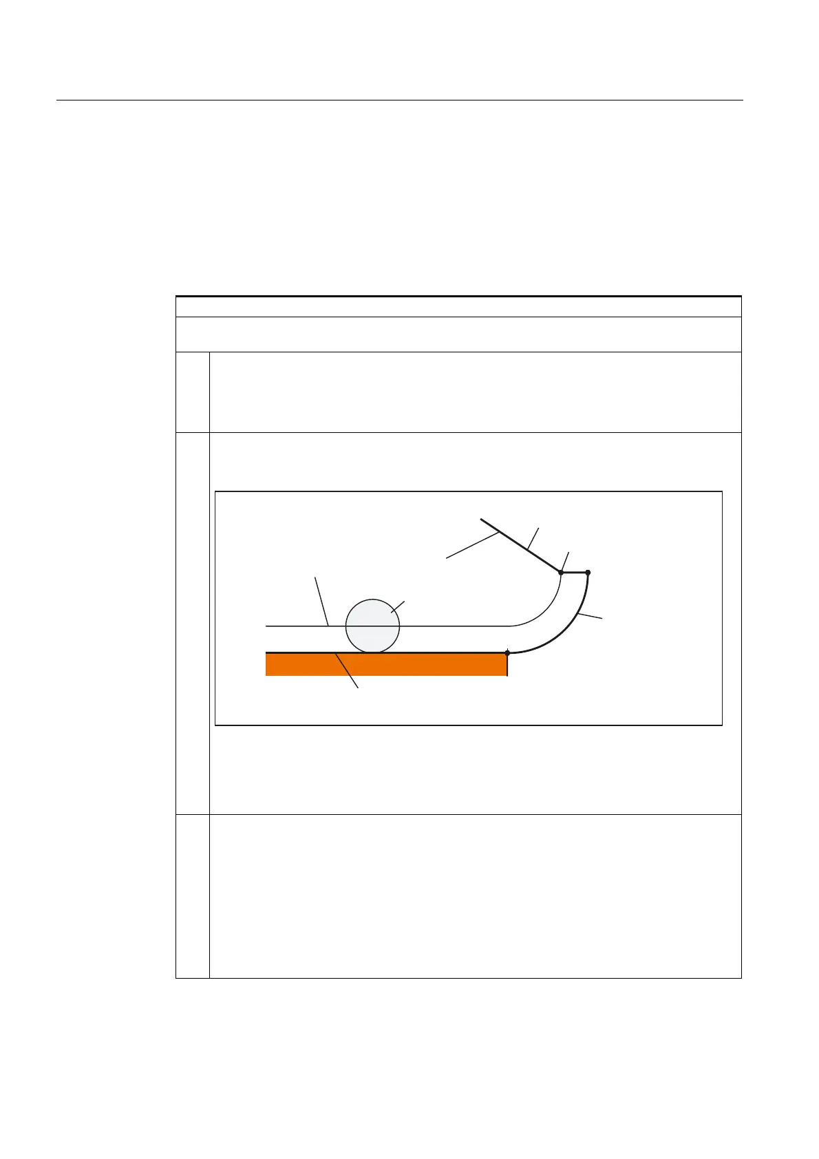
6$5EORFN
**
7RROFHQWHUSDWK
7RRO
&RQWRXUSUHFHGLQJEORFN
)ROORZLQJEORFNZLWKRXWRIIVHW
3
3
3
Retraction with SAR with simultaneous deactivation of TRC
If the SAR retraction block is also used to deactivate tool radius compensation, in the case of 1.
and 2., an additional path from P
1
to P
0
is inserted such that no movement is produced when
tool radius compensation is deactivated at the end of the retraction contour, i.e., this point
defines the tool center point and not a position on a contour to be corrected.
3 At least one axis of the machining plane is programmed. The second axis of the machining
plane can be determined modally from its last position in the preceding block. The position of
the axis perpendicular to the machining plane is generated as described in 1. or 2., depending
on whether this axis is programmed or not. The position generated in this way defines the end
point P
0
.
No special measures are required for deselection of tool radius compensation, because the
programmed point P
0
already directly defines the position of the tool center point at the end of
the complete contour.
The start and end points of the SAR contour (P
0
and P
4
) can coincide on approach and
retraction.
 Loading...


