Detailed Description
2.4 Tool: Tool radius compensation 2D (TRC)
Tool Compensation (W1)
2-54 Function Manual, 08/2005 Edition, 6FC5397-0BP10-0BA0
$TC_DP1[1,1]=120 ; Milling tool T1/D1
$TC_DP6 [1,1] = 7 ; Tool with 7 mm radius
N10 G90 G0 X0 Y0 Z20 D1 T1
N20 G41 G341 G247 DISCL=AC(5) DISR=13FAD 500 X40 Y-10 Z=0 F2000
N30 X50
N40 X60
...
• Programming feed F
This feed value is effective from point P
3
(or from point P
2
, if FAD is not programmed). If
no F command is programmed in the SAR block, the speed of the preceding block is
valid. The velocity defined by FAD is not used for following blocks.
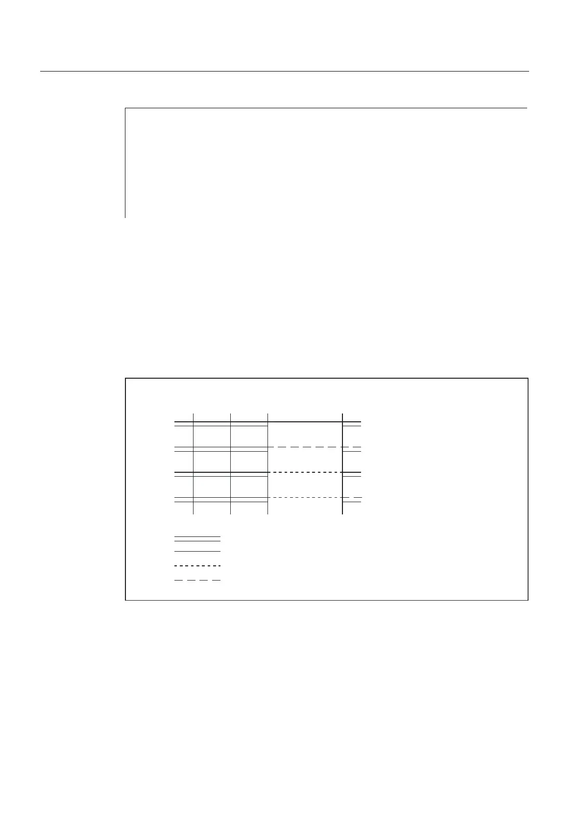
Velocities
In both approach diagrams below, it is assumed that no new velocity is programmed in the
block following the SAR block. If this is not the case, the new velocity comes into effect after
point P
4
.
1RYHORFLW\SURJUDPPHG
2QO\)SURJUDPPHG
2QO\)$'SURJUDPPHG
)DQG)$'SURJUDPPHG
9HORFLW\RISUHFHGLQJEORFNROG)FRPPDQG
,QIHHGYHORFLW\SURJUDPPHGZLWK)$'
1HZPRGDOYHORFLW\SURJUDPPHGZLWK)
5DSLGWUDYHUVHLI*LVDFWLYHRWKHUZLVHZLWKWKHROGRUQHZ)FRPPDQG
3
3333
Fig. 2-21 Velocities in the SAR subblocks on approach with G340
 Loading...


