Detailed Description
2.4 Tool: Tool radius compensation 2D (TRC)
Tool Compensation (W1)
2-58 Function Manual, 08/2005 Edition, 6FC5397-0BP10-0BA0
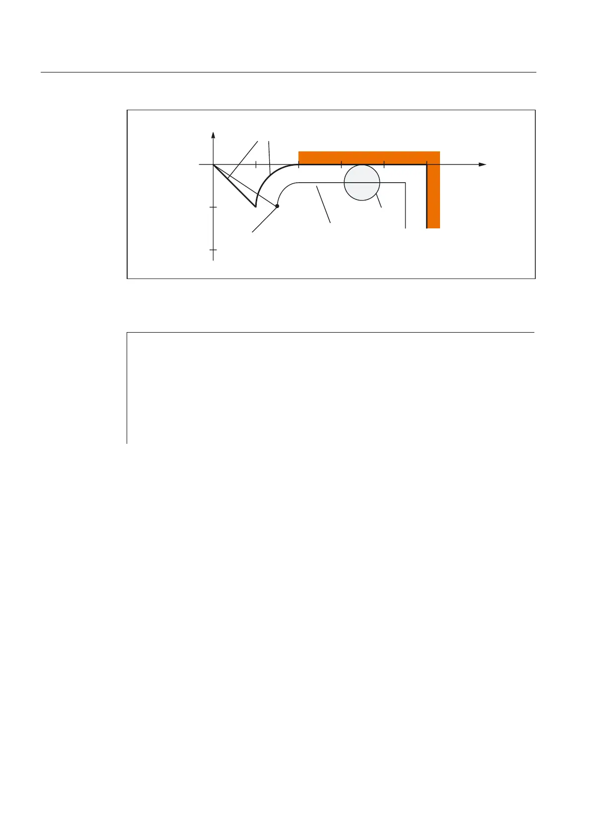
6$5FRQWRXU
7RRO
,QIHHG
PRYHPHQWLQ=
7RROFHQWHUSDWK
;
<
Fig. 2-24 Contour example 1
Part program:
$TC_DP1[1,1]=120 ; Tool definition T1/D1
$TC_DP6 [1,1] = 10 ; Radius
N10 G0 X0 Y0 Z30
N20 G247 G341 G42 NORM D1 T1 Z0 FAD=1000 F=2000 DISCL=5 DISR=10
N30 X40
N40 X100
N50 Y-30
...
Example 2
The following conditions must be true for approach:
• Smooth approach is activated in block N20
• Approach movement performed with quadrant (G247)
• Approach direction not programmed, G140 is valid, i.e., because TRC is active (G41), the
contour is approached from the left
• Contour compensation OFFN=5 (N10)
• Current tool radius=10, and so the effective compensation radius for TRC=15; the radius
of the SAR contour is thus equal to 25, with the result that the radius of the tool center
path is equal to DISR=10
• The end point of the circle is obtained from N30, since only the Z position is programmed
in N20
• Infeed movement
– From Z20 to Z7 (DISCL=AC(7)) with rapid traverse
– Then on to Z0 with FAD=200
– Approach circle in X/Y plane and following blocks with F1500. (For this velocity to be
active in the following blocks, the active G code G0 must be overwritten in N30 with G1.
Otherwise, the contour would continue to be machined with G0.)
 Loading...


