Detailed Description
2.5 Toolholder with orientation capability
Tool Compensation (W1)
2-88 Function Manual, 08/2005 Edition, 6FC5397-0BP10-0BA0
It is permissible for the two vectors v
1
and v
2
to be zero. A change in orientation is then no
longer possible. In this special case, any lengths l
1
and l
2
, which are not equal to zero, act as
additional tool length compensations, in which the components in the individual axes are not
affected by changing the plane (G17 - G19).
Kinematics data expansions
• Possibility of direct access to existing machine axes in order to define the toolholder
setting via the rotary axis positions.
• Extension of the kinematics with rotary workpiece and on kinematics with rotary tool and
rotary workpiece.
• Possibility to permit only discrete values in a grid for the rotary axis positions (Hirth tooth
system).
The extensions are compatible with earlier software versions and encompass the kinematic
data blocks from $TC_CARR18 to $TC_CARR23.
Machine with rotary tool
On machines with rotary tool there is no change in the definition of the kinematics compared
to older software versions. The newly introduced vector l
4
, in particular, has no significance.
Should the contents of l
4
not be zero, this is ignored.
The term "Toolholder with orientation capability" is actually no longer really appropriate for
the new kinematic types, with which the table can also be rotated, either alone or additionally
to the tool. However, it has been kept for reasons of compatibility.
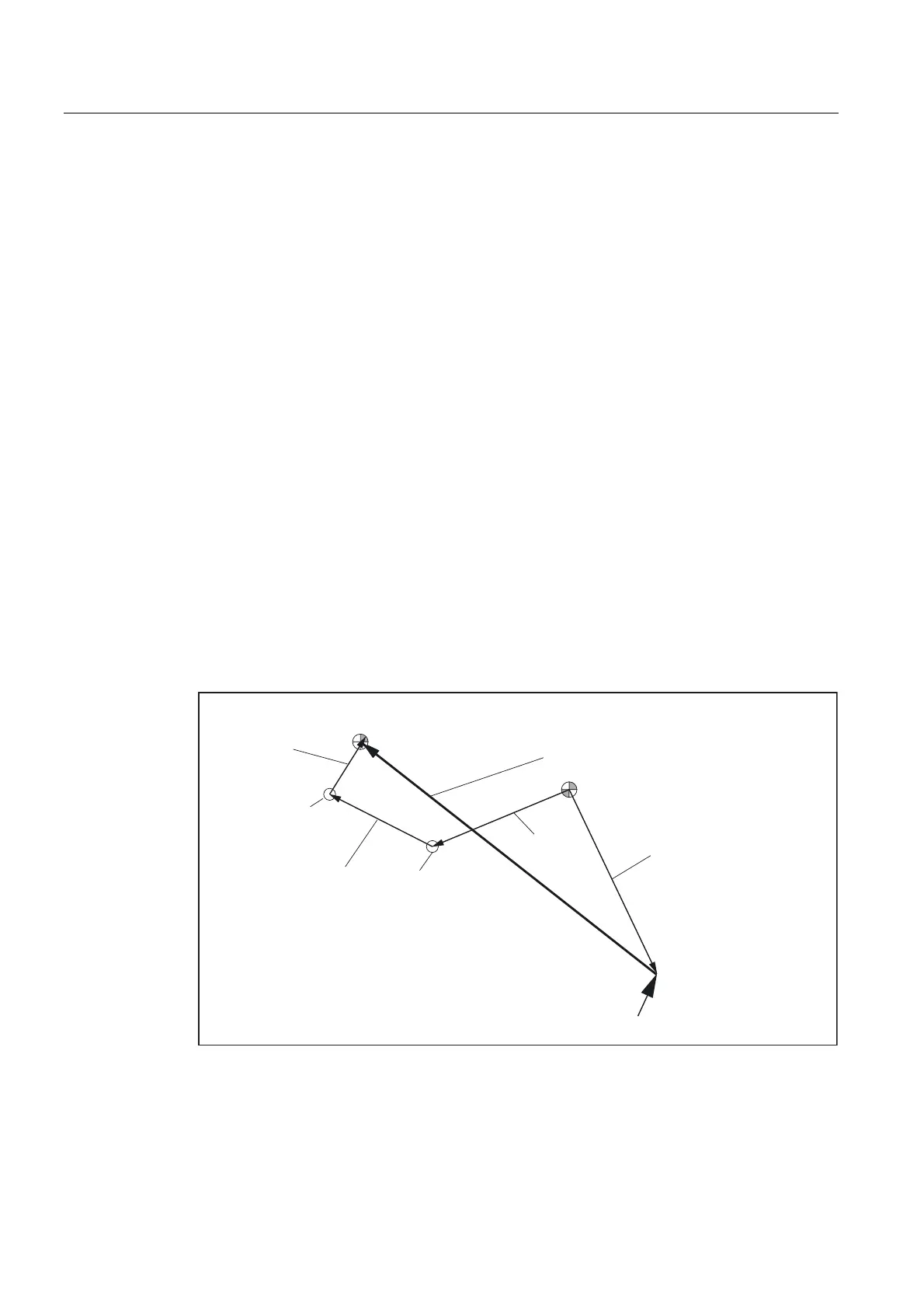
The kinematic chains used to describe the machine with rotary tool (general case) are shown
in the figure below:
7RROOHQJWK
ZHDU
WRROEDVHGLPHQVLRQ
7RROUHIHUHQFH
SRLQW
7RROKROGHUUHIHUHQFHSRLQW
5HVXOWLQJWRROOHQJWKFRPSHQVDWLRQ
7RRORULHQWDWLRQ
O
O
Y
˞
Y
˞
O
Fig. 2-42 Kinematic chain to describe a tool with orientation
Vectors, which describe offsets in the rotary head, are positive in the direction from the tool
tip to the reference point of the toolholder.
 Loading...


