Detailed Description
2.5 Toolholder with orientation capability
Tool Compensation (W1)
Function Manual, 08/2005 Edition, 6FC5397-0BP10-0BA0
2-89
The following kinematic type is defined for machines with a rotary tool:
$TC_CARR23 using letter T
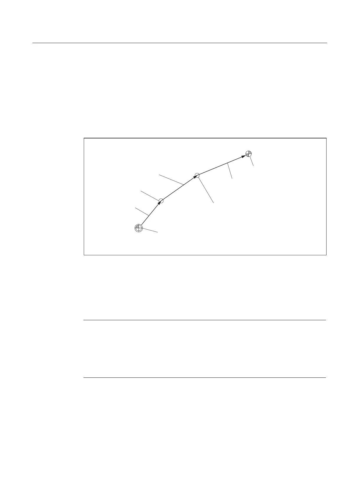
Machine with rotary workpiece
On machines with rotary workpiece, the vector l
1
has no significance. If it contains a value
other than zero, this is ignored. The kinematic chain for machines with rotary workpiece is
shown in the figure below.
0DFKLQHUHIHUHQFHSRLQW
5HIHUHQFHSRLQWRI
WKHWRROWDEOH
O
Y
˞
Y
˞
O
O
Fig. 2-43 Kinematic chain to describe a rotary table
Vectors, which describe offsets in the rotary table, are positive in the direction from the
machine reference point to the table.
The following kinematic type is defined for machines with a rotary workpiece:
$TC_CARR23 using letter P
Note
On machines with rotary workpiece it is generally useful if the selected machine reference
point and the reference point of the table are identical. Selecting the reference points in this
way has the advantage that the position of the workpiece zero in the initial state (i.e., with
rotary axes not turned) does not change when the rotary table is activated. The (open)
kinematic chain (see figure) is then closed.
In this special case, therefore, the following formula applies: l
2
= - (l
3
+ l
4
)
Machines with extended kinematics
On machines with extended kinematics (both tool and workpiece are rotary), it is only
possible to turn each of the components with one axis.
 Loading...


