Detailed Description
2.5 Toolholder with orientation capability
Tool Compensation (W1)
2-90 Function Manual, 08/2005 Edition, 6FC5397-0BP10-0BA0
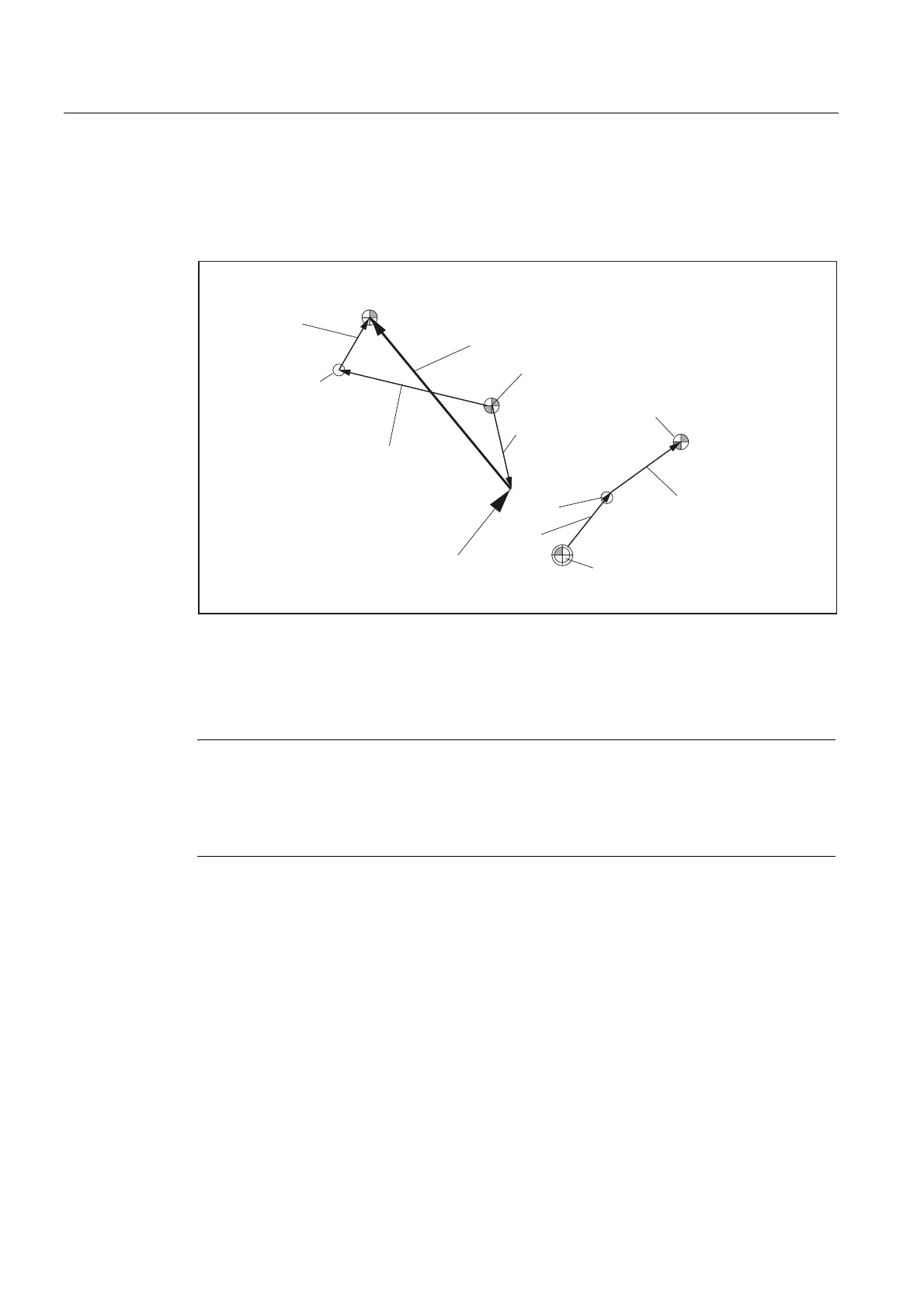
The kinematic of the rotary tool is described with the first rotary axis (v
1
) and the two vectors
l
1
and l
2
, that of the rotary table with the second rotary axis (v
2
) and the two vectors l
3
and l
4
.
The two kinematic chain components for machines with rotary tool and rotary workpiece are
shown in the figure below.
7RROOHQJWK
ZHDU
WRROEDVHGLPHQVLRQ
5HVXOWLQJWRROOHQJWKFRPSHQVDWLRQ
5HIHUHQFHSRLQWRIWKH
WRROKROGHU
7RRORULHQWDWLRQ
5HIHUHQFHSRLQWRI
WKHWRRO
0DFKLQHUHIHUHQFHSRLQW
5HIHUHQFHSRLQWRI
WKHWRROWDEOH
O
O
Y
˞
O
O
Y
˞
Fig. 2-44 Kinematic sequence with extended kinematics
The following kinematic type is defined for machines with a rotary tool and rotary workpiece:
$TC_CARR23 using letter M (extended kinematics)
Note
On machines with extended kinematics it is generally useful, as with machines where only
the table can be rotated, for the machine reference point and the reference point of the table
to be identical. The (open) chain component to describe the table (see figure) is then closed.
In this special case, the following formula applies: l
3
= - l
4
Rotary tool types T and M
For machine kinematics with a rotary tool (types T and M), the toolholder component with
orientation capability, which describes the tool or head component (as opposed to the table
component), acts, in conjunction with the active tool, as a new overall tool.
 Loading...


