Brief Description
1.2 Overview of auxiliary functions
Auxiliary Function Output to PLC (H2)
Function Manual, 08/2005 Edition, 6FC5397-0BP10-0BA0
1-7
DL functions
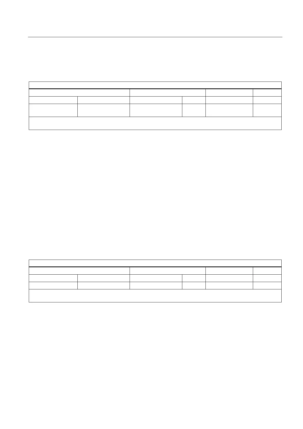
DL (additive tool offset)
Address extension Value
Value range Meaning Value range Type Meaning Number
8)
- - - - - - 0 - 6 INT Selection of the
additive tool offset
1
Remarks:
The additive tool offset selected with DL refers to the active D number.
Application
Selection of the additive tool offset with reference to an active tool offset.
Remarks
• Initial setting: DL = 0
• DL values cannot be output to the PLC via synchronized actions.
• Default setting of the additive tool offset without an active DL function:
MD20272 $MC_SUMCORR_DEFAULT
• Deselection of the additive tool offset: DL = 0
• DL-function-specific machine data:
– MD22252 $MC_AUXFU_DL_SYNC_TYPE
F functions
F (feedrate)
Address extension Value
Value range Meaning Value range Type Meaning Number
8)
- - - - - - 0.001 - 999 999.999 REAL Path feed 6
Remarks:
- - -
Application
Path velocity.
Remarks
• F-function-specific machine data:
– MD22240 $MC_AUXFU_F_SYNC_TYPE
 Loading...


