Detailed Description
2.7 Program operation mode
Mode Group, Channel, Program Operation, Reset Response (K1)
Function Manual, 08/2005 Edition, 6FC5397-0BP10-0BA0
2-105
Interrupt signals
A total of 8 interrupt signals are available.
All inputs can be controlled from the PLC.
In addition, the first four interrupt signals are controlled via the 4 rapid NC inputs on the
NCU module (X121).
The signal state of the rapid NC inputs can be read out via the PLC interface (DB10).
Transmission of the rapid NC input signals to the interrupt signals can be disabled via the
PLC interface (DB10).
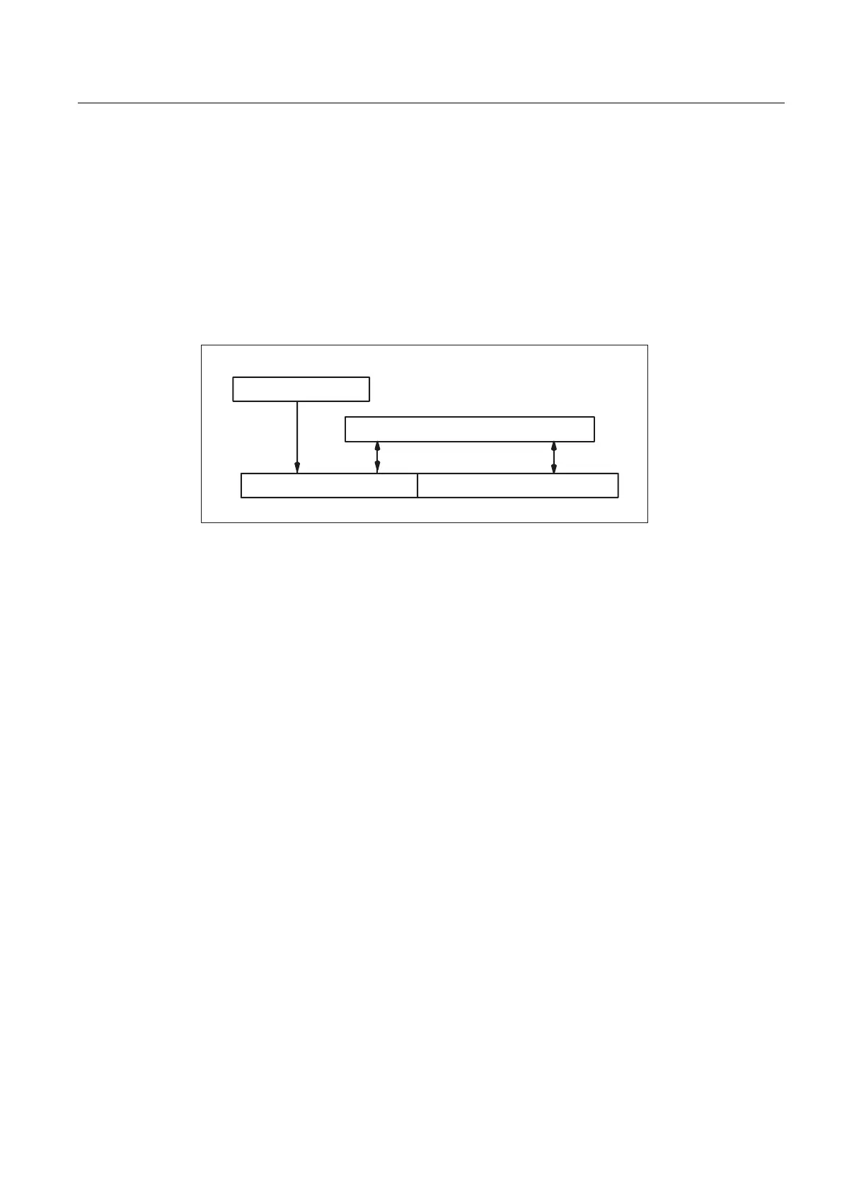
PLC interface
4 interrupt signals
4 rapid NC inputs
4 interrupt signals
Fig. 2-12 Interrupt signals
For further information about PLC control of the rapid NC inputs (interrupt signals) see:
References: /FB2/, A4, "Digital and Analog NCK I/Os"
Activation of interrupt routine
Interrupt routines can be activated by two different methods:
• By a 0/1 transition of the interrupt signal, triggered by a 0/1 transition at the rapid
NC input
• By the call of function call ASUPST (/B1/, /P3/)
Upon activation, all machine axes are decelerated to a standstill according to the
acceleration ramp (MD32300 $MA_MAX_AX_ACCEL (axis acceleration)), and the axis
positions are stored.
Reorganization
In addition to decelerating the axes, the previously decoded calculation blocks are calculated
back to the interruption block. i.e., all the variables, frames and G codes are assigned the
value that they would have at the point of interruption if the part program had not been
previously decoded. These values are put in the buffer so that they can be called up again
when the interrupt routine is completed.
 Loading...


