Detailed Description
2.1 Motion monitoring functions
Axis Monitoring, Protection Zones (A3)
2-8 Function Manual, 08/2005 Edition, 6FC5397-0BP10-0BA0
Note
The NC detects whether an axis is clamped based on the "servo enable" state of the axis:
DB31, ... DBX2.2 = 0 (servo enable): no servo enable ⇒ axis is clamped
DB31, ... DBX2.2 = 1 (servo enable): servo enable ⇒ axis is not clamped
Prerequisites for the PLC user program
• The axis is always removed from the clamp when a travel command is pending.
• The following is always valid for the axis:
DB31, ... DBX2.2 = 0 (servo enable): Axis is clamped
DB31, ... DBX2.2 = 1 (servo enable): Axis is not clamped
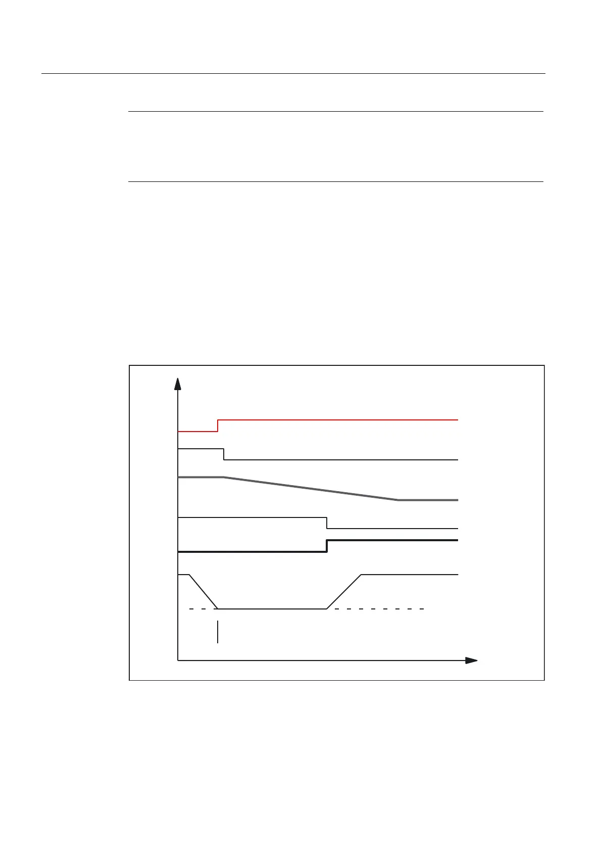
The following image shows an example of the interface signals and states upon releasing of
the axis clamp. The part program blocks N310 and N410 refer to the schematic example
under certain boundary conditions.
W>PV@
5HOHDVHD[LVFODPSIRU
0'6723B21B&/$03,1*>@ +
&ODPSD[LV
)HHGVWRS
0RWLRQFRPPDQG
&RQWUROOHUHQDEOH
3DWKYHORFLW\
1
*=
1
*$7XUQURWDU\WDEOHGHJUHHV
$[LVFODPSLQJSUHVVXUH
Fig. 2-3 Example 1: Interface signals and states
 Loading...


