Detailed Description
2.4 Frames
Axis Types, Coordinate Systems, Frames (K2)
2-100 Function Manual, 08/2005 Edition, 6FC5397-0BP10-0BA0
If MOVT is programmed, linear or spline interpolation must be active (G0,G1, ASPLINE,
BSPLINE, CSPLINE). Otherwise, an alarm is produced.
If a spline interpolation is active, the resultant path is generally not a straight line, since the
end point calculated by MOVT is treated as if it had been programmed explicitly with X, Y, Z.
A block with MOVT must not contain any programming of geometry axes (alarm 14157).
Definition of frame rotations with solid angles
Where a frame is to be defined to describe a rotation around more than one axis, this is
achieved through chaining individual rotations. A new rotation is hereby always performed in
the already rotated coordinate system.
This is also the case when programming in a block, e.g., with ROT X... Y... Z...
(the sequence of rotations is defined by machine data
MD10600 $MN_FRAME_ANGLE_INPUT_MODE
and is independent of the sequence of the axis letters in the block),
and when constructing a frame in multiple blocks, e.g., in the format:
N10 ROT Y...
N20 AROT X...
N30 AROT Z...
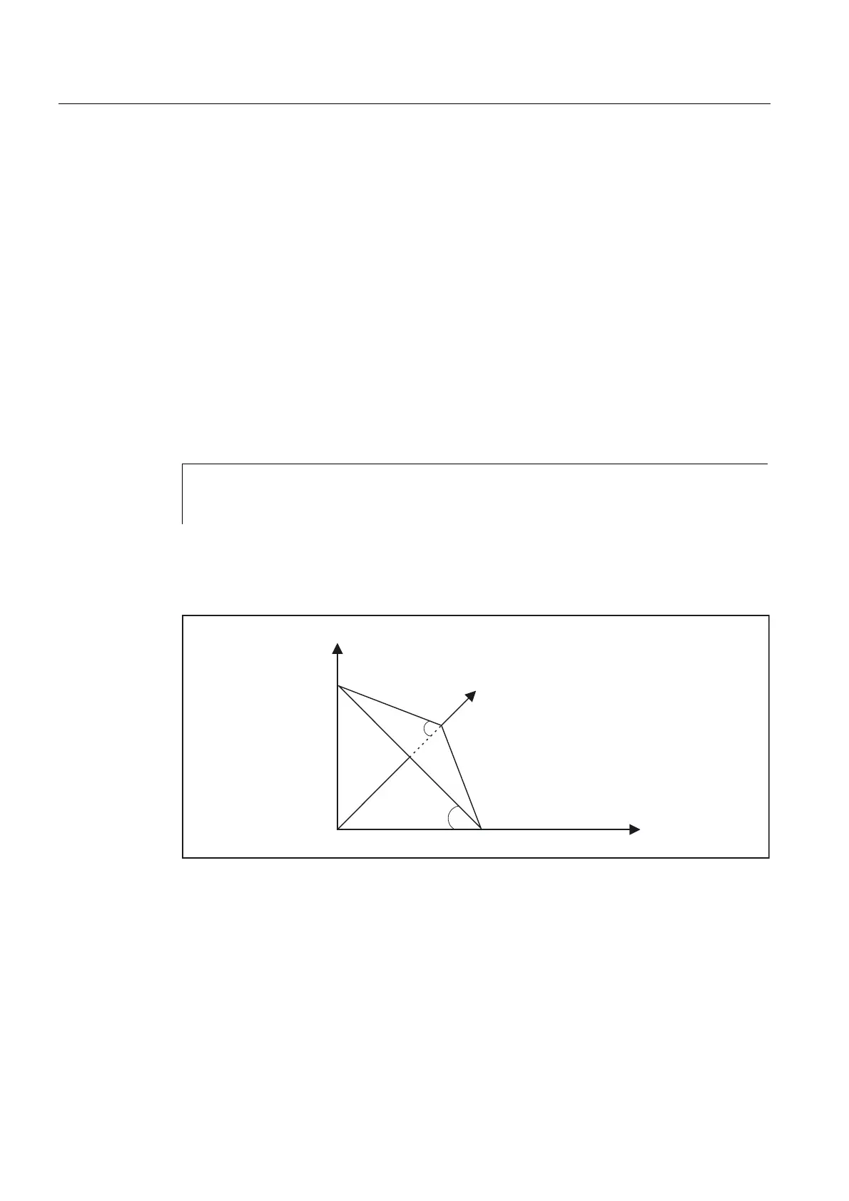
In workpiece drawings, oblique surfaces are frequently described by way of solid angles, i.e.,
the angles, which the intersection lines of the oblique plane form with the main planes
(X-Y, Y-Z, Z-X planes) (see figure). The machine operator is not expected to convert these
solid angles into the angles of rotation of a chaining of individual rotations.
\
[
]
\
[
2EOLTXHSODQH
For this reason, the language commands ROTS, AROTS and CROTS are used, with which the
rotations can be immediately described as solid angles.
The orientation of a plane in space is defined unambiguously by specifying two solid angles.
The third solid angle is derived from the first two. Therefore, a maximum of 2 solid angles
may be programmed, e.g., in the form ROTS X10 Y15. If a third solid angle is specified, an
alarm will be triggered.
 Loading...


