Configuration
86
7SS52 V4 Manual
C53000-G1176-C182-3
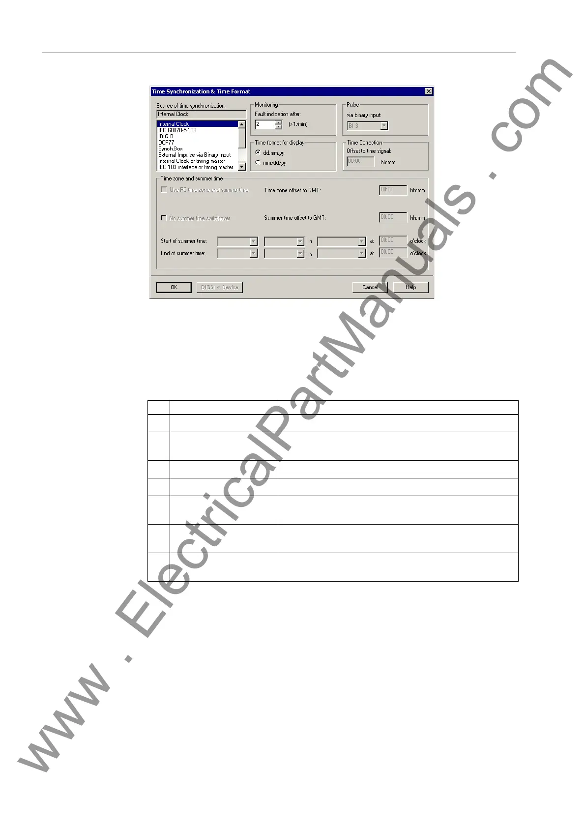
Figure 4-35 Time Synchronization & Time Format dialog box in DIGSI − Example
Specify here the factors for influencing the internal clock management. You can
choose between the following operating modes:
Due to the internal buffer battery the RTC continues to run even when the auxiliary
voltage is switched off temporarily. RTC is always the first synchronization source for
the internal clock management when the device is switched on or after a failure of the
auxiliary voltage regardless of the set operating mode.
In the operating mode Internal Clock the internal clock management uses only
RTC as the synchronization source. It can also be changed manually. The manual set-
ting of date and time is described in Chapter 6.3.7, page 239.
If one of the external operating modes is selected, only the parameterized synchroni-
zation source will be used. If it fails, the internal clock will continue in unsynchronized
mode.
Table 4-3 Operating modes of the clock management
No. Operating mode Comments
1 Internal Clock Internal synchronization via RTC (default)
2 IEC 60870-5-103 External synchronization via IEC 60870-5-103−system in-
terface
3 Time signal IRIG B External synchronization via IRIG B
4 Time signal DCF77 External synchronization via the time signal DCF77
5 Time signal Sync.
Box
External synchronization via the time signal SIMEAS-
Synch.Box
6 External Impulse
via Binary Input
External synchronization with impulse via
binary input
7 NTP (IEC 61850) External synchronization via system interface
(IEC 61850)
www . ElectricalPartManuals . com

 Loading...


