Home
Siemens
Power distribution unit
SIPROTEC 7SS522 V4.6
Siemens SIPROTEC 7SS522 V4.6 User Manual
5
of 1
of 1 rating
440 pages
Give review
Manual
Specs
To Next Page
To Next Page
To Previous Page
To Previous Page
Loading...
Functions
136
7SS52 V4 Manual
C53000-G1176-C182-3
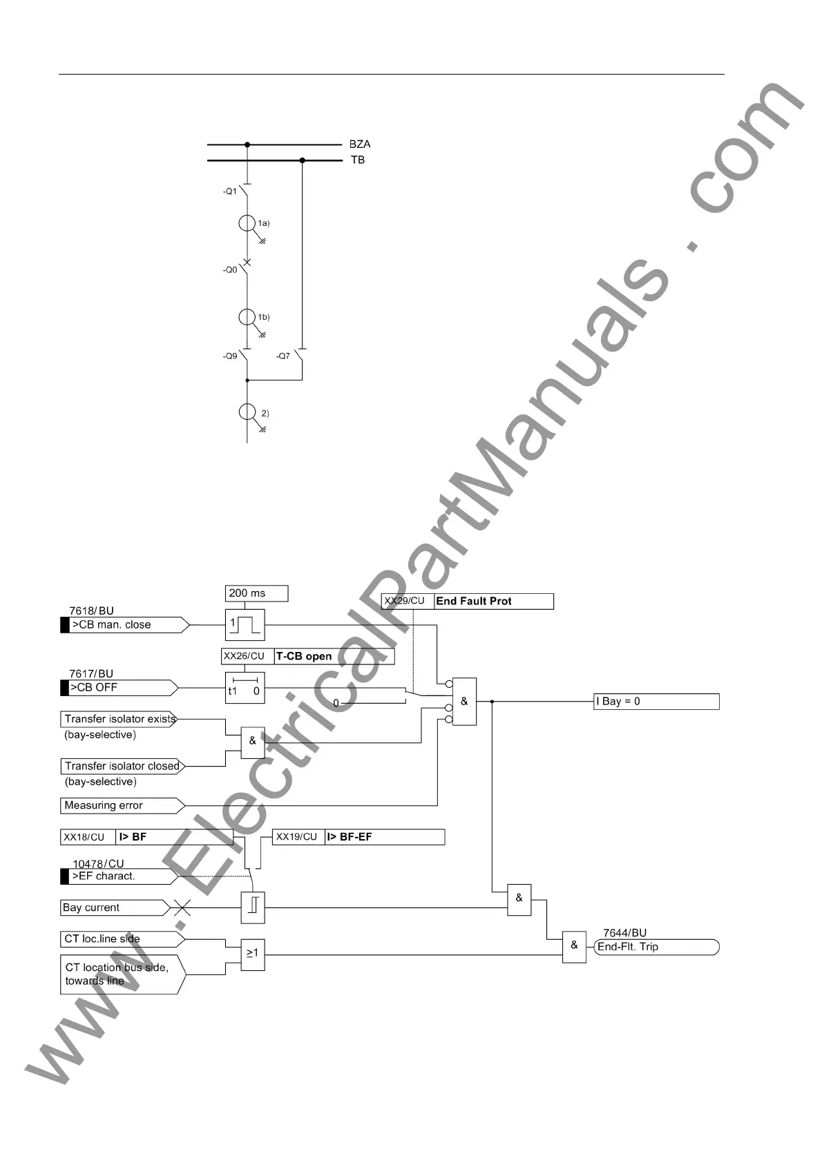
Figure 5-28
Possible CT locations
Figure 5-29
End fault protection
CT location:
1a) inside (relating to Q7) current transf
ormers, busbar side (relating to Q0
)
1b) inside (relating to Q7) current transf
ormers, line side (relating to Q0)
2) line-side current transformers (
relating to Q7)
www
.
ElectricalPartManuals
.
com
151
153
Table of Contents
Default Chapter
7
Table of Contents
7
1 Introduction
17
Overall Operation
18
C53000-G1176-C182
19
Applications
20
Configuration
20
Features
21
Functions
21
2 Design and Connection System
29
General
30
Central Unit
31
Front View
31
Modules and Submodules
32
Design
33
Bay Unit
34
Front View
34
Modules and Submodules
35
Design
37
Panel Surface Mounting
37
Panel Flush Mounting or Cubicle Mounting
37
Connection Method
38
Location of Device Connections
38
Device Connections
41
Screw-Type Terminals
42
Double Leaf-Spring-Crimp Contacts
42
D-SUB Female Connectors
43
Fiber-Optic Cable Connections
43
EN100 Module Ethernet (IEC 61850)
44
3 Getting Started
45
Unpacking and Repacking
46
Checking the Rated Data
46
Matching the Control Voltage for the Binary Inputs and Inserting the Buffer Battery
47
Electrical Checks
54
Setting up the Communication between the Central Unit
55
And the Bay Unit
55
Operation of SIPROTEC Devices from the Operator Panel
56
User Interface
56
Navigating the Operating Tree of the Display
56
Setting Addresses in the Bay Unit
57
Adjusting the Display Contrast
59
Storage
60
4 Configuration
61
Creating a Project
62
Inserting Central Unit / Bay Units
63
Plant Configuration
65
How to Proceed
65
Starting the Plant Configuration
66
Drawing Busbars
68
Defining Bays
70
Inserting Dynamic Elements
72
Connecting Dynamic Elements to the Busbars
74
Inserting Lines
74
Inserting a Connection
75
Normalized Current
76
Inserting Static Text
77
Creating and Inserting Typicals
78
4.3.10 Saving the Substation Chart
78
Configuration Notes
79
Assigning Bay Units
87
Marshalling
89
Marshalling Information Items of the Central Unit
89
Allocable Information
89
Marshalling
90
Marshalling Bay Unit Information
92
Allocable Information
92
Marshalling
93
Settings
96
Serial Ports
97
Date/Clock Management
101
Concluding the Configuration
105
5 Functions
107
Busbar Protection
108
Mode of Operation
108
Basic Principle
108
Algorithm with Instantaneous Values
110
Separate Evaluation of Half-Cycles
112
Evaluation of the Initial Values
115
Algorithm with Filtered Values
116
Summary of the Measuring Method
116
Isolator Replica
117
Bus Coupler Variants
119
Bus Couplers with One Current Transformer
119
Bus Couplers with Two Current Transformers
120
Bus Couplers Without Circuit Breaker
120
Bus Couplers with more than 5 Isolators
120
Combi-Coupler
120
Transfer Busbars
121
Transfer Busbar with Inside Transformers
123
Special Cases of Transfer Busbar Operation
123
Setting Notes
124
Settings for the Central Unit
127
Check Zone
128
Mode of Operation
128
Setting Notes
129
Settings for the Central Unit
129
Circuit Breaker Failure Protection
130
Characteristics for the Circuit Breaker Failure Protection
130
Setting Notes
131
Settings for the Central Unit
132
List of Information from the Central Unit
132
Bay-Specific Functions (BU)
133
Triggering and Releasing the Breaker Failure Protection
133
Circuit Breaker Failure Protection During a Feeder Short-Circuit
135
Circuit Breaker Failure Protection for Busbar Faults
142
Failure of the Bus Coupler Circuit Breaker
143
Circuit Breaker Not Ready
143
Setting Notes
144
Settings for the Central Unit
148
List of Information from the Central Unit
149
List of Information from the Bay Unit
150
End Fault Protection
151
Protection with Fault in the "Dead Zone" of the Bus Coupler
153
With Detection of the Circuit-Breaker Position, Circuit Breaker Open
154
Setting Notes
155
Supervisory Functions
156
Auxiliary and Reference Voltages
158
Output Trip Supervision
159
Cyclic Test
160
Isolator Status Supervision
162
Supervisory of Circuit Breaker
167
Overview of the Supervisory Functions
168
Setting Notes
170
Settings for the Central Unit
173
List of Information from the Central Unit
174
List of Information from the Bay Unit
175
Oscillographic Fault Recording
176
Setting Notes
177
Settings for the Central Unit
178
Device
179
Settings for the Central Unit
181
Power System Data
182
Protection General
183
Operating States "Bay out of Service", "Maintenance Mode
184
Overcurrent-Controlled TRIP Command
185
Feeder-Selective Trip Release
186
Busbar Tripping Via an External Signal
187
Setting Notes
188
Settings for the Central Unit
190
List of Information from the Central Unit
191
List of Information from the Bay Unit
192
Bay Unit
193
Integrated Operation of the Bay Unit
194
Settings of the Bay Unit
195
PC Port of the Bay Unit
196
Settings of the Bay Unit
197
Fault Recording in the Bay Unit ("Local Fault Recording")
198
Settings of the Bay Unit
199
Scope of Protective Functions in the Bay Unit
200
Settings of the Central Unit
201
Power System Data of the Bay Unit
202
Settings of the Central Unit
203
Overcurrent Protection in the Bay Unit
204
Setting Notes
206
Settings of the Bay Unit
211
List of Information from the Bay Unit
212
User-Defined Annunciations
213
Setting Notes
215
Settings of the Bay Unit
216
List of Information from the Bay Unit
217
Backup Breaker Failure Protection in the Bay Unit
218
Setting Notes
222
Settings of the Central Unit
223
List of Information from the Bay Unit
224
6 Control During Operation
225
Overview
226
Reading out Information
228
Operational Annunciations
230
Fault Events
232
Alarm List
233
General Interrogation
234
Statistics
235
Reading out Fault Data
237
Controlling Device Functions
241
Blocking
242
Blocking the Breaker Failure Protection
246
Blocking of Individual Busbar Sections
248
Saving and Deleting Annunciations
249
Deleting Annunciations
250
Circuit Breaker Test
251
Reset Blocking
253
Reset Blocking of Isolator Fault
254
Read and Set Date / Time
255
Feeder Shutdown and Commissioning
260
Maintenance Mode
263
Plant Visualization
265
Installation and Commissioning
271
7 Installation and Commissioning
272
Bay Unit
273
General Information on the 2-Bay Bus Coupler
274
Bay Bus Coupler with 2 Current Transformers
275
Connection
276
Checking the Connections
277
Commissioning
278
How to Proceed
279
Web Monitor
280
Functions
281
Checking the Switching States of the Binary Inputs/Outputs
284
Bay Unit
287
Testing the System Port
289
Control of the Isolator Replica
291
Switching the Test Mode and the Transmission Block on and off
293
Checks with Secondary Values
294
Trip Characteristic of the Busbar Protection
295
Check Zone
297
Differential Current Monitoring
299
Check Zone
300
Overcurrent Threshold Tripping
301
Delay Time at Operating Mode "Unbalancing" and "I>Query
302
Checks with Primary Values
303
Final Check of the Protection
304
8 Maintenance and Repair
305
Maintenance
306
Fault Analysis
308
Checking the Auxiliary Voltage Supply
309
Analysis of Internal Communication Failures
311
Troubleshooting
315
Repair
318
Replacing the Buffer Battery
319
Replacing the Fine-Wire Fuse
322
Startup with a Defective Bay Unit / Defective Fiber-Optic Cable
325
9 Technical Data
327
General Data
328
General Device Data
329
Binary Inputs
330
Trip Contacts
331
Serial Ports
332
Busbar Protection
333
Circuit Breaker Failure Protection
334
Overcurrent Protection in the Bay Unit
335
Auxiliary Functions
337
User-Configurable Functions (CFC)
338
Electrical Tests
339
Mechanical Tests
341
Climatic Stress Tests
342
Service Conditions
343
Mcbs for Device 7Ss52X
344
Dimensions
345
Bay Unit
347
A.1 Data for Selection and Ordering
352
A.1.2 Bay Units
353
A.1.3 Accessories
354
A.2 Basis for Selection of the Stabilization Factor K
357
A.3 Connection Diagrams
358
A.4.1 Settings of the ZPS Modules
364
A.4.2 Settings of the EAZ Module
368
A.4.3 Jumper Settings of the D-CPU Module
370
A.5.1 Settings of the PFE Module
372
A.5.2 Settings of the SVW Module
373
A.5.3 Settings of the SAF Module
374
A.5.4 Settings of the AFE Module
375
A.5.5 Settings of the EFE Module
376
A.5.6 Settings of the EFE_10 Module
378
A.6 Protocol-Dependent Functions
380
A.7 Parameter Listing - Central Unit
381
A.8 Parameter Listing - Bay Unit
383
A.9 List of Information - Central Unit
389
A.10 List of Information - Bay Unit
399
A.11 Group Alarms - Central Unit
405
A.12 Group Alarms - Bay Unit
408
A.13 Measured Value List - Central Unit
409
A.14 Measured Value List - Bay Unit
410
A.15 Marshalling - Central Unit
411
A.16 Marshalling - Bay Unit 7SS523
414
A.17 Marshalling - Bay Unit 7SS525
417
A.18 Navigation Tree - Central Unit
419
A.19 Navigation Tree of the Bay Unit
429
A.20 Abbreviations
430
A.21 References
431
5
Based on 1 rating
Ask a question
Give review
Questions and Answers:
Need help?
Do you have a question about the Siemens SIPROTEC 7SS522 V4.6 and is the answer not in the manual?
Ask a question
Siemens SIPROTEC 7SS522 V4.6 Specifications
General
Brand
Siemens
Model
SIPROTEC 7SS522 V4.6
Category
Power distribution unit
Language
English
Related product manuals
Siemens SIPROTEC 7SS523 V3.3
440 pages
Siemens SIPROTEC 7SS525 V3.3
440 pages
Siemens SIPROTEC 7SS523 V3.2
440 pages
Siemens SIPROTEC 7SJ46
77 pages
Siemens SIPROTEC 4 7SD80
416 pages
Siemens SIPROTEC 7XR81
70 pages
Siemens SIPROTEC 7RW600
168 pages
Siemens SIPROTEC 7XR8004
70 pages
Siemens SIPROTEC 4 7VE61
330 pages
Siemens SIPROTEC 5 V8.30
292 pages
Siemens SIPROTEC 5 V8.83
296 pages
Siemens SIPROTEC 5 Series
254 pages