Installation and Commissioning
280
7SS52 V4 Manual
C53000-G1176-C182-3
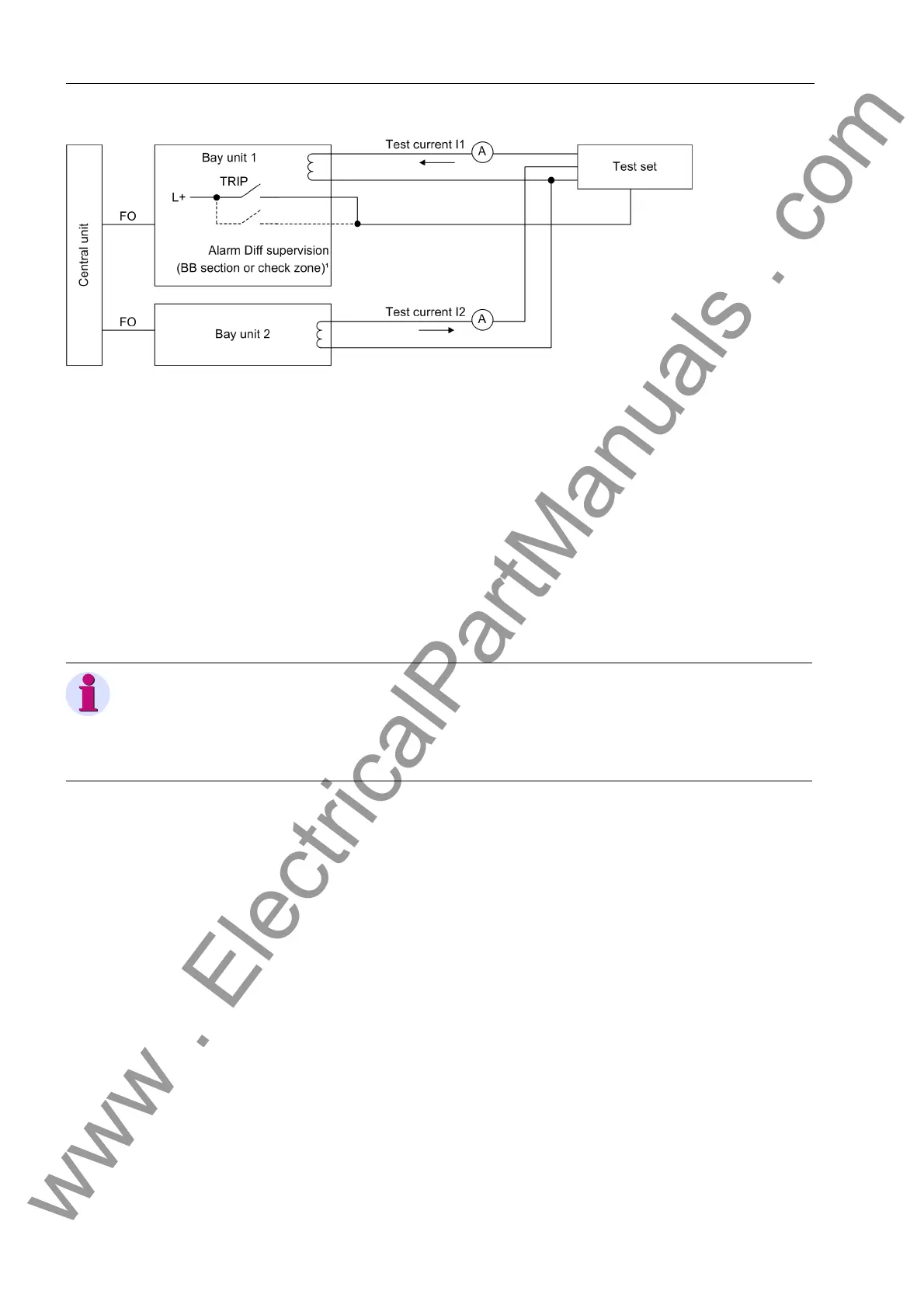
Figure 7-11 Test setup for the trip characteristic of the busbar-selective measuring system
Test steps To prevent that the differential current supervision from blocking the protection dur-
ing the test switch it off with the parameter DIFF SUPERV (6306/CU).
Set the differential current threshold and the stabilization factor for the busbar-se-
lective protection and the check zone as desired.
Set the parameters I>TRIP (XX13/CU) for the overcurrent thresholds for the affect-
ed bays to 0.
The test currents I
1
and I
2
must have a phase displacement of 180°. To find out the
phase angle, check the feeders 1 and 2 each with the same current (0.5 I
N
).
If the connection is correct the differential current must be nearly zero and the sta-
bilization current must be the double of the supply current.
If the differential current in not zero, check the connection. If that is correct reverse
the polarity in a feeder.
If the current I
2
is zero, then increase the current I
1
for so long until a TRIP com-
mand is output. The current in the feeder must correspond to the differential current
threshold set in the parameter Id> BZ (6102/CU).
Apply a constant current I
1
which is smaller than the set differential current thresh-
old to the feeder 1 from the test setup
Increase the current I
2
in feeder 2 slowly until the protection trips.
The following fomulas are valid:
Differential current I
d
= | I
1
+ I
2
|
Stabilizing current I
s
= | I
1
| + | I
2
|
Stabilizing factor k = I
d
/ I
s
= | I
1
+ I
2
| / (| I
1
| + | I
2
|)
1 For testing the diff-current limit for supervisory function (refer to Chapter 7.3.3, page 268)
Note
The percentages of the differential and stabilization currents refer to Normalized Cur-
rent (Chapter 4.3.7, page 60). The percentages of the feeders refer to the transformer-
rated value of the particular feeder. If the same percentages are displayed this does
not mean necessarily that the same current is flowing in the concerned feeders.
www . ElectricalPartManuals . com

 Loading...


