Installation and Commissioning
282
7SS52 V4 Manual
C53000-G1176-C182-3
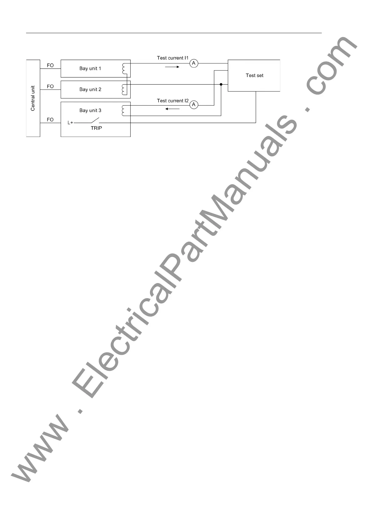
Figure 7-13 Test setup for the trip characteristic of the check zone.
Test steps Prevent the differential current supervision from blocking the protection during the
tests switch it off with the parameter DIFF SUPERV (6306/CU).
Set the differential current threshold and the stabilization factor for the busbar-se-
lective protection and the check zone as desired.
Set the parameters I>TRIP (XX13/CU) for the overcurrent limits for the affected
bays to 0.
The test current I
1
in bay unit 1 and 2 must have a phase shift of 180°. To find out
the phase angle, check the feeders 1 and 2 each with the same current (0,5 I
N
).
If the connection is correct the differential current of the bus zone must be nearly
zero and the stabilization current must be the double of the supply current.
If the differential current is not zero, reverse the polarity in a feeder.
If the current I
1
is zero, increase the current I
2
until the annunciation Trip L1 CZ
to Trip L3 CZ (FNo. 10457 to 10459/CU) is output by the measuring system
which is assigned to bay 3. The current I
2
must correspond to the differential current
threshold set in the parameter Id> CZ (6104/CU).
Apply to the bays 1 and 2 of the test setup with a constant current I
1
.
Increase the current I
2
in bay 3 slowly until the protection trips. The differential cur-
rent is then I
2
and the stabilizing current I
1
(Chapter 5.2, page 112). The stabilizing
factor k is then equal to the ratio of I
2
to I
1
.
Repeat the test with different constant currents I
1
. The trip characteristic graph is
shown in Figure 7-12, page 281.
www . ElectricalPartManuals . com

 Loading...


